Container with integral module for heating or cooling the contents

a technology of container and module, applied in the field of containers, can solve problems such as the consumption of container contents, and achieve the effect of relieving pressure and reducing pressure through apertures

Inactive Publication Date: 2006-10-10
GRP II PARTNERS L P AS LENDER +7
View PDF70 Cites 64 Cited by
  • Summary
  • Abstract
  • Description
  • Claims
  • Application Information

AI Technical Summary

Benefits of technology

[0014]In accordance with one aspect of the present invention, a plastic thermic module body is spin-welded to a plastic container body by rotating one relative to and in contact with the other. The frictionally generated heat fuses or welds the contacting plastic surfaces together. The container body may have multiple layers, including an oxygen and flavor scalping barrier layer that inhibits oxidation and spoilage of the contents. Spin-welding the container body to the module body in this manner seals the portion of the inner layer that is exposed at the annular end of the container body between two plastic layers and thereby prevents air or moisture from seeping past the outer plastic layer and into the inner layer.
[0015]In accordance with still another aspect of the present invention, the thermic module body has a heat exchanger portion having a pleated wall. The pleated design is provided with relatively large radii at the peaks and valleys of the pleats. The heat exchanger portion also has a plurality of circumferential grooves which longitudinally separate the pleated portions. The large radii and grooves help prevent the thermic module from failing under the pressure and temperature of the retort process.
[0017]In accordance with still another aspect of the invention, the thermic module includes a seal, such as a foil disc, between an inner actuator button and an outer actuator button. The inner actuator button may be included in a module cap that holds the solid reactant. The outer actuator button has one or more apertures and also has one or more prongs directed toward the seal. When the user presses the outer actuator button, the prong punctures the seal. This actuator structure eliminates the disposal problem associated with a removable foil seal. In addition, if for some reason the module cap were to become over-pressurized prior to use, the pressure would force the inner actuator button against the seal. The seal, in turn, presses against the prong and punctures it, thereby relieving the pressure through the apertures in the outer actuator button.
[0018]In another aspect of the present invention, as an alternative to the outer actuator button and tamper-evident foil disc, the container comprises a full panel pull-off attached to the bottom of the container. A full panel pull-off is a removable cover like those used on canned foods and is like a typical pop-tab closure (e.g. the closure on a soft-drink or soup metal can) except that the lid part that is removable covers substantially the entire opening of the container rather than just a small opening. The full panel pull-off completely covers the inner actuator button and may be made of aluminum such that the actuator button cannot be pushed until the full panel pull-off is removed. The full-panel pull-off provides a tamper-evident seal and also protects the actuator button from being inadvertently pushed. The full panel pull-off may also provide a pressure safety release valve. In the event that the breakable barrier is pushed without removing the full panel pull-off, pressure will build up inside the container because the vent holes in the thermic module vent only to the interior of the full panel pull-off. If the pressure reaches a certain level, the full panel pull-off will partially open thereby relieving the pressure.

Problems solved by technology

The user may then open the closure and consume the contents of the container.

Method used


Image

  • Container with integral module for heating or cooling the contents
  • Container with integral module for heating or cooling the contents
  • Container with integral module for heating or cooling the contents

Examples


Embodiment Construction

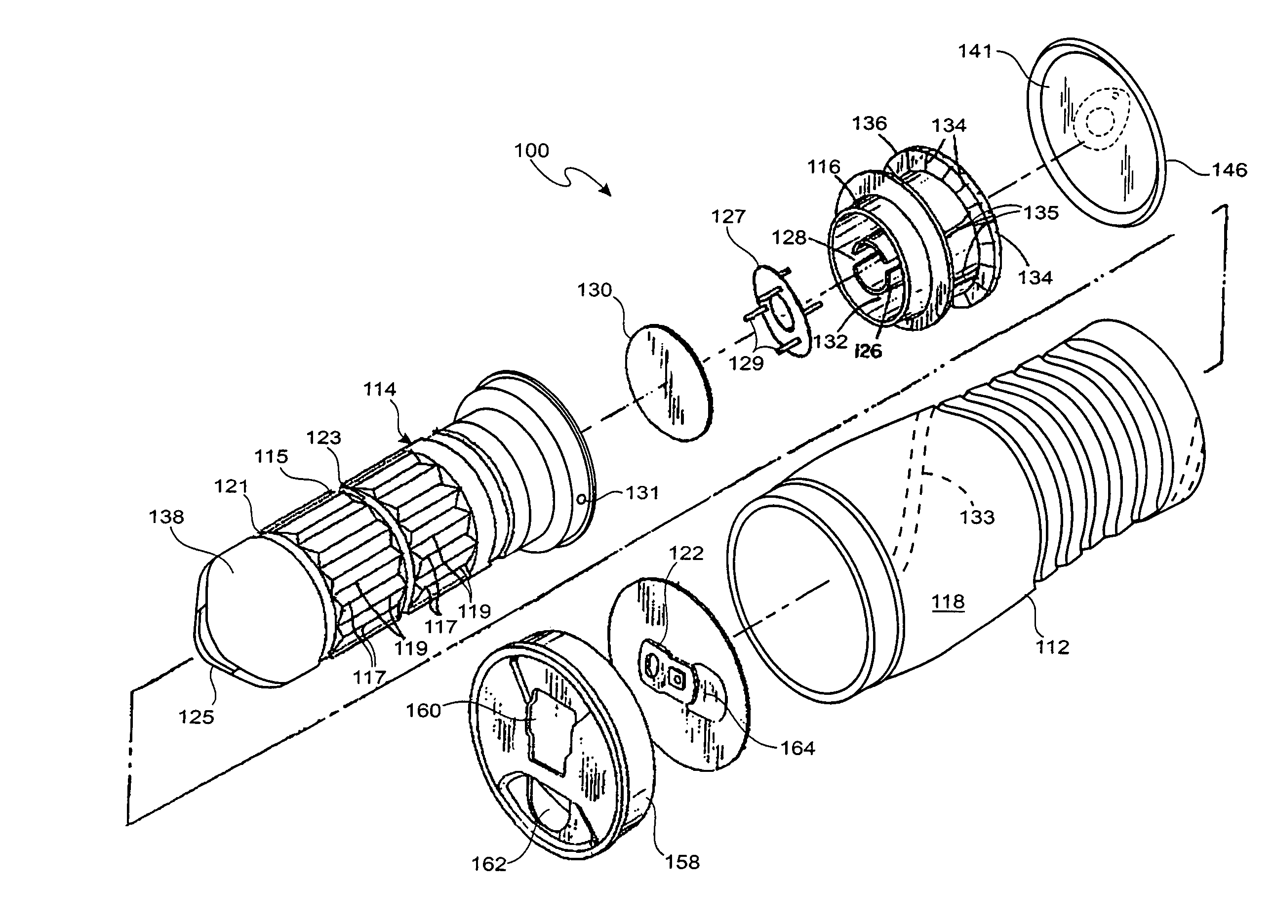
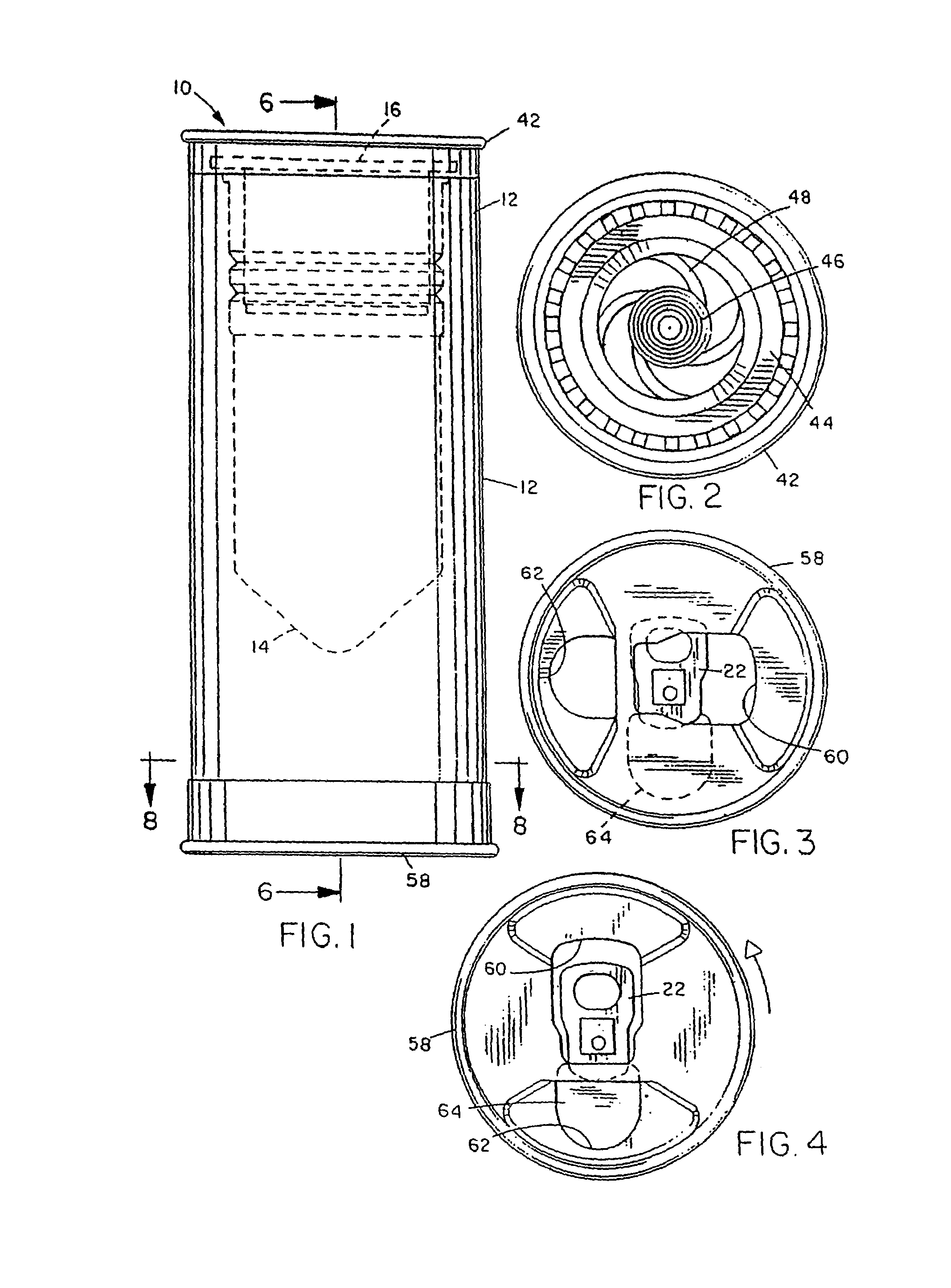
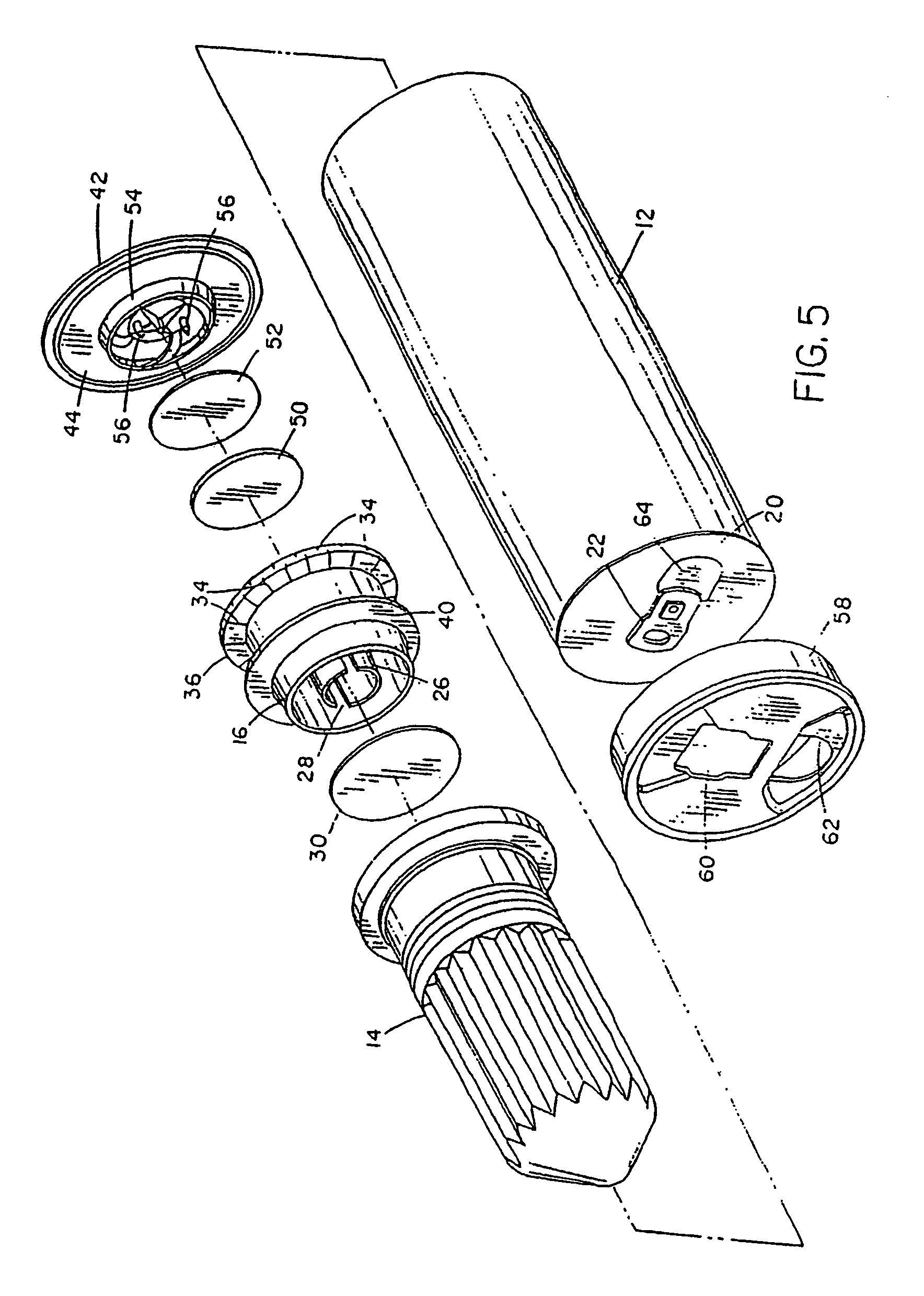
[0046]As illustrated in FIGS. 1–8, a container 10 includes a container body 12, a thermic module body 14, and a thermic module cap 16. As best illustrated in FIGS. 5–7, module body 14 has an elongated heat-exchanger portion that extends into container body 16. The interior of this portion defines a reaction chamber in which the reaction occurs that heats (or, in alternative embodiments of the invention, cools) the beverage or other contents 18. The heat-exchanger portion has a corrugated or pleated wall to increase surface area and, as a result, heat transfer. Although in the illustrated embodiment the wall is corrugated or pleated, in other embodiments the wall may have other suitable geometries. Module cap 16 is press-fit in the open end of module body 14. An endcap 20 with a pop-tab closure 22 of the type commonly used in beverage cans is crimped over the other end of container body 12 in the manner of a conventional beverage can.

[0047]Module cap 16 is of unitary construction and...


PUM


Abstract

A container comprises a container body for containing contents to be heated or cooled, a thermic module at one end of the body, and a closure at the other end of the body. Within the thermic module, an internal exothermic (or, alternatively, endothermic) chemical reaction is initiated to heat its contents when a user actuates the thermic module. The thermic module includes a heat exchanger portion extending proximally into the container and a thermic module cap distal to the heat exchanger portion. The heat exchanger portion has a pleated wall to improve the heat transfer to the contents of the container. The container includes a rotatable cover adhered to the container end over the closure with heat-sensitive adhesive that prevents a user from accessing the contents until a certain temperature is reached. The container further includes a full panel pull-off which covers and protects the actuator from being actuated until the pull-of lid is removed from the full panel pull-off. The thermic module may also include a filter disposed in interfering relation with the thermic module vents, including a portion between the inner and outer actuator buttons, to block egress of any particles of the solid reactant or the reaction product.

Description

BACKGROUND OF THE INVENTION[0001]1. Field of the Invention[0002]The present invention relates generally to containers that include an internal module that adds heat to or removes heat from a material, such as a food, beverage, medicine, or the like, in the surrounding container.[0003]2. Description of the Related Art[0004]Containers may have integral modules for warming materials in the container, such as sake, coffee, or soup. Examples of such self-heating containers are disclosed in U.S. Pat. Nos. 5,461,867; 5,626,022; and 6,351,953 issued to Scudder et al. All patents, patent applications and other publications referenced in this application are hereby incorporated by reference herein in their entirety. Such containers typically include an outer can or body, in which the food or beverage is sealed, and an inner can or thermic module that contains two chemical reactants that are stable when separated from one another but, when they mix in response to actuation of the thermic modul...

Claims


Application Information

Patent Timeline
Patent Type & Authority Patents(United States)
IPC IPC(8): F25D5/00F24J1/00F24J3/00F24V30/00F25D5/02
CPCF25D5/02F25D2331/805F25D2500/02
Inventor SCUDDER, JAMES A.BOUCHER, DAVID C.KAPITZKE, PETER J.SANDERMAN, KENNETH M.
Owner GRP II PARTNERS L P AS LENDER
Why Eureka
Try Eureka