Device for monitoring maintenance and adjustment of pressure in a tire

a technology for monitoring and maintenance, applied in vehicle tyre testing, roads, instruments, etc., can solve the problems of user failure to observe, inability to ensure the optimum inflation of tires, and time-consuming inflation methods, so as to achieve simple design, improve safety, and avoid energy supply.

Inactive Publication Date: 2006-10-10
SITHOLD SRO
View PDF6 Cites 82 Cited by
  • Summary
  • Abstract
  • Description
  • Claims
  • Application Information

AI Technical Summary

Benefits of technology

[0022]The device has the advantage to contain at least one first sensor chosen from the group consisting of a tire press sensor, a tire profile sensor, a chamber profile sensor, a chamber volume sensor, a sensor of difference between the pressure inside the chamber and the tire inside space pressure, or a sensor of the difference between pressures inside the chamber and the outside environment pressure, and possibly at least one second sensor chosen from the group consisting of a tire velocity sensor or a tire acceleration sensor.
[0034]One of the variants of the device is able to monitor the driving style and adjust the optimum tire pressure by means of controls. The device reduces fuel consumption, increases safety and extends the tire life.

Problems solved by technology

These inflation methods are time consuming and require periodical checks of pressure, which the users often fail to observe.
These methods moreover do not ensure optimum inflation of a tire in a situation when the current driving manners differ from the manner the tire was originally inflated for.
This affects either the tire itself by extensive wear, or safety, as the tire is not always able to perform as it should e.g. as a result of lower pressure to road surface.
A badly inflated tire has higher rolling resistance, which increases fuel consumption.
This solution is relatively complicated, it requires a compressor in the vehicle, and transfer of compressed air to the rotating wheel is also complicated.
This device is attached to the tire with a belt, which is not very convenient and may threaten the traffic safety.
When the pressure inside the tire exceeds the critical value of the shrinkable hose, this deforms and does no longer enable the chamber to suck gas from the outside environment.
Manufacturing of the shrinkable hose and adjustment of the moment of its deformation and thus the maximum pressure in the chamber is technologically demanding.
The device is relatively complicated.
A chamber designed this way, with just one non-return valve, like the patent RU 2106978 does not enable cumulating of gas in the chamber for more cycles.

Method used


Image

  • Device for monitoring maintenance and adjustment of pressure in a tire
  • Device for monitoring maintenance and adjustment of pressure in a tire
  • Device for monitoring maintenance and adjustment of pressure in a tire

Examples


example 1

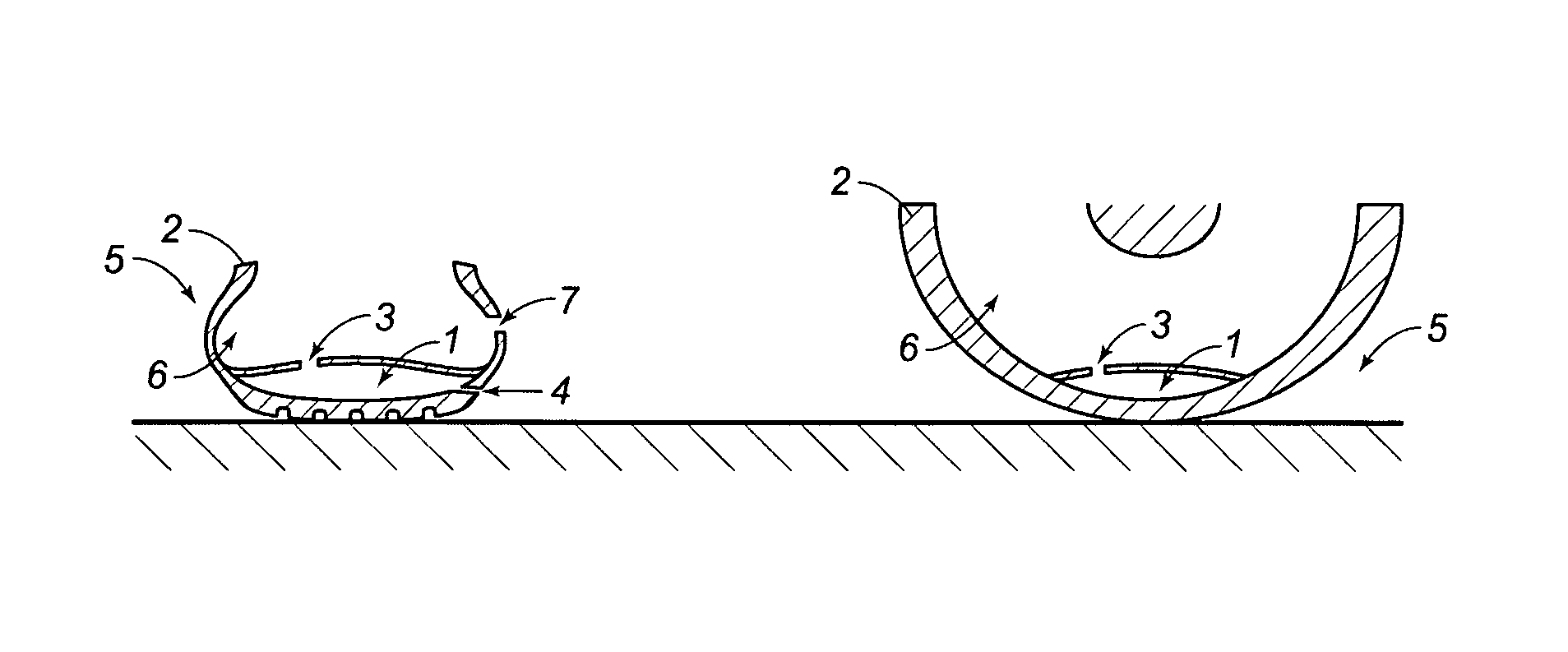
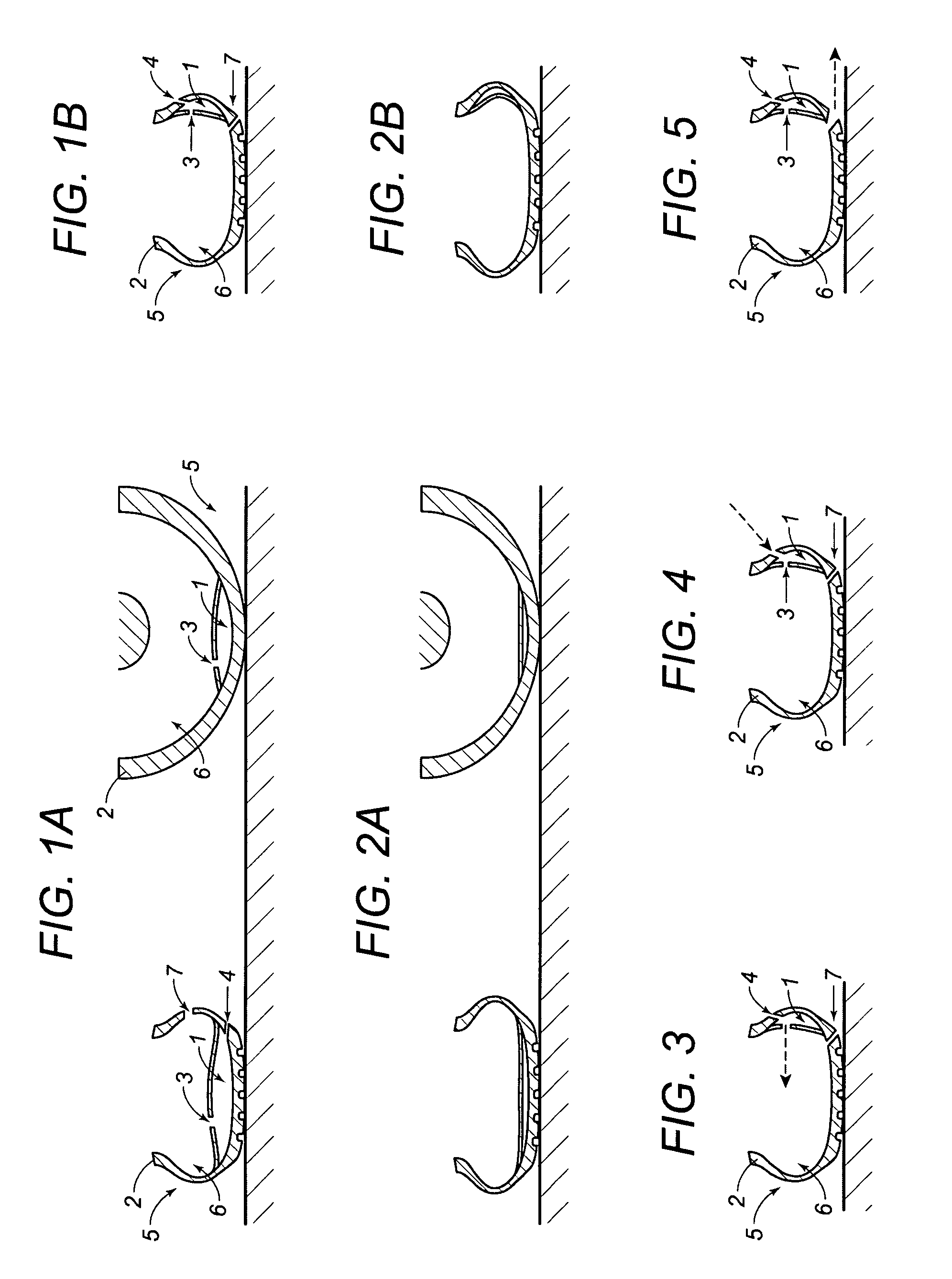
[0049]FIG. 1a) shows a tire 2, fitted with the device for monitoring, maintenance and adjustment of pressure in the tire 2. The device consists of a chamber 1, one wall of which is a part of the wall of the tire 2 tread, while the chamber 1 is connected through one internal valve 3 to the inside space 6 of the tire 2, it is then connected with one external valve 4 with the outside environment 5.

[0050]The chamber 1 volume is at its maximum at the moment when no load deforming the tire 2 caused by rolling of the tire 2 is applied. The chamber 1 is filled by the air from the outside environment 5 through the external valve 4.

[0051]When the tire 2 starts rolling on the road and is deformed at the place where the chamber 1 is located, higher pressure is generated in the chamber 1 than in the inside space 6 of the tire 2. The chamber 1 volume is reduced. The pressure is defined by unloaded volume of the chamber 1 or its part and volume of chamber 1 or its part when loaded, multiplied by t...

example 2

[0055]FIG. 1b) shows a tire 2, fitted with the device for monitoring, maintenance and adjustment of pressure in the tire 2. The device consists of a chamber 1 located in the case at the side of the tire 2. The chamber 1 is connected with the inside space 6 of the tire 2 through one internal valve 3, with the outside environment 5 through one external valve 4 and the inside space 6 of the tire 2 is connected with the outside environment 5 through the third valve 7. The tire 2 deformed by the load is shown in FIG. 3. The pressure inside the chamber 1 is higher than inside space 6 the tire 2, the internal valve 3 is open and the gas from the chamber 1 flows to the inside space 6 of the tire 2. The gas flow direction is indicated by a broken arrow.

[0056]The tire 2 during finishing the load deformation or after the load deformation is shown in FIG. 4.

[0057]The external valve 4 is open and the gas from the outside environment 5 flows to the chamber 1. The gas flow direction is indicated b...

example 3

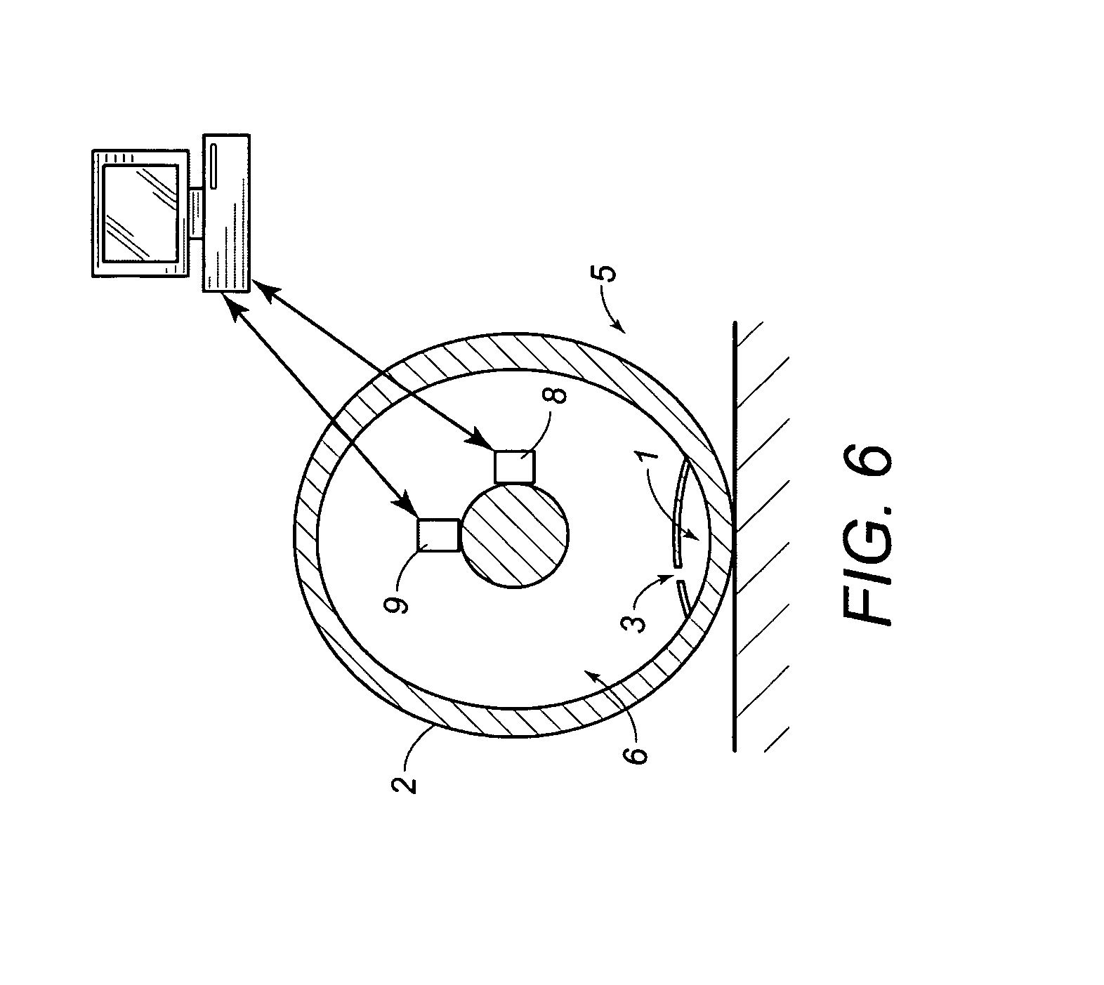
[0059]A convenient situation is, when the chamber 1 is longer then the length of the optimum contact surface of the tire 2, e. g. the length of the chamber 1 is a half of the tire 2 perimeter.

[0060]The chamber 1 is divided during the load deformation into two parts, the first one, where the load deformation has already occurred, and the second one, where the deformation is just under way. The walls of the chamber 1 are pressed hermetically to each other during the course of the load deformation of both the above parts of the chamber 1 and compressed gas is accumulated in the second part of the chamber 1. The gas pressure in the second part of the chamber 1, where the hermetic contact has not occurred yet increases proportionally to the decrease of the volume of the part of the chamber 1.

[0061]A chamber 1 designed this way prevents accidental or inconvenient inflation of the inside space 6 of the tire 2 if the load deformation is caused e. g. by a stone.

[0062]Suitable length and-suit...


PUM


Abstract

Device for monitoring, maintenance and / or adjustment of pressure in a tire includes the chamber with shape memory deformable for the period of application of external mechanical forces when the tire rolls on the road surface, connected valve with the inside space of the tire and valve with the outside environment. At least one wall of the chamber is adjacent to the inside wall of the tire or is a part of the inside wall of the tire. Furthermore, the device operates on the peristaltic pump principle consisting of the chamber, which is deformable up to the zero cross section. At least one chamber with block with shape memory is freely open at one end and equipped with at least one valve at the other end or next to it. The minimum volume of the part of the chamber at the end equipped with the internal valve or external valve is from 1 to 80% of the total maximum volume of the chamber.

Description

RELATED U.S. APPLICATIONS[0001]Not applicable.STATEMENT REGARDING FEDERALLY SPONSORED RESEARCH OR DEVELOPMENT[0002]Not applicable.REFERENCE TO MICROFICHE APPENDIX[0003]Not applicable.FIELD OF THE INVENTION[0004]The invention deals with monitoring, maintenance and adjustment of pressure in a tire in dependence on current or long-term way of its usage.BACKGROUND OF THE INVENTION[0005]Tires are usually inflated with gas when the vehicle is stopped, by external compressors and pumps nowadays. These inflation methods are time consuming and require periodical checks of pressure, which the users often fail to observe.[0006]These methods moreover do not ensure optimum inflation of a tire in a situation when the current driving manners differ from the manner the tire was originally inflated for. This affects either the tire itself by extensive wear, or safety, as the tire is not always able to perform as it should e.g. as a result of lower pressure to road surface. The economical point of vi...

Claims


Application Information

Patent Timeline
Patent Type & Authority Patents(United States)
IPC IPC(8): G01M17/02B60C23/12
CPCB60C23/12B60C23/123B60C23/135
Inventor HRABAL, FRANTISEK
Owner SITHOLD SRO
Why Eureka
Try Eureka