Valve for changing the direction of flow of a fluid in pipe conduits

Inactive Publication Date: 2006-10-10
MARINNOVATION
View PDF10 Cites 8 Cited by
  • Summary
  • Abstract
  • Description
  • Claims
  • Application Information

AI Technical Summary

Benefits of technology

[0007]Another difficulty with the known valve according to SE 504 895 is that dirt and particles are collected in the space between the cylindrical casing and the pipes, and if a too large amount is accumulated the rotation of the valve body can be difficult or in the worst case be prevented. In order to secure the rotating function, the valve house has to be drained regularly during operation, which means that the valve house must be provided with a drain connection. Since the val

Problems solved by technology

The shapes of these two pipes are quite complex and demand a complicated and expensive method of production.
Another difficulty with the known valve according to SE 504 895 is that dirt and particles are collected in the space between the cylindrical casing and the pipes, and if a too large amount is accumulated the rotation

Method used


Image

  • Valve for changing the direction of flow of a fluid in pipe conduits
  • Valve for changing the direction of flow of a fluid in pipe conduits
  • Valve for changing the direction of flow of a fluid in pipe conduits

Examples


Embodiment Construction

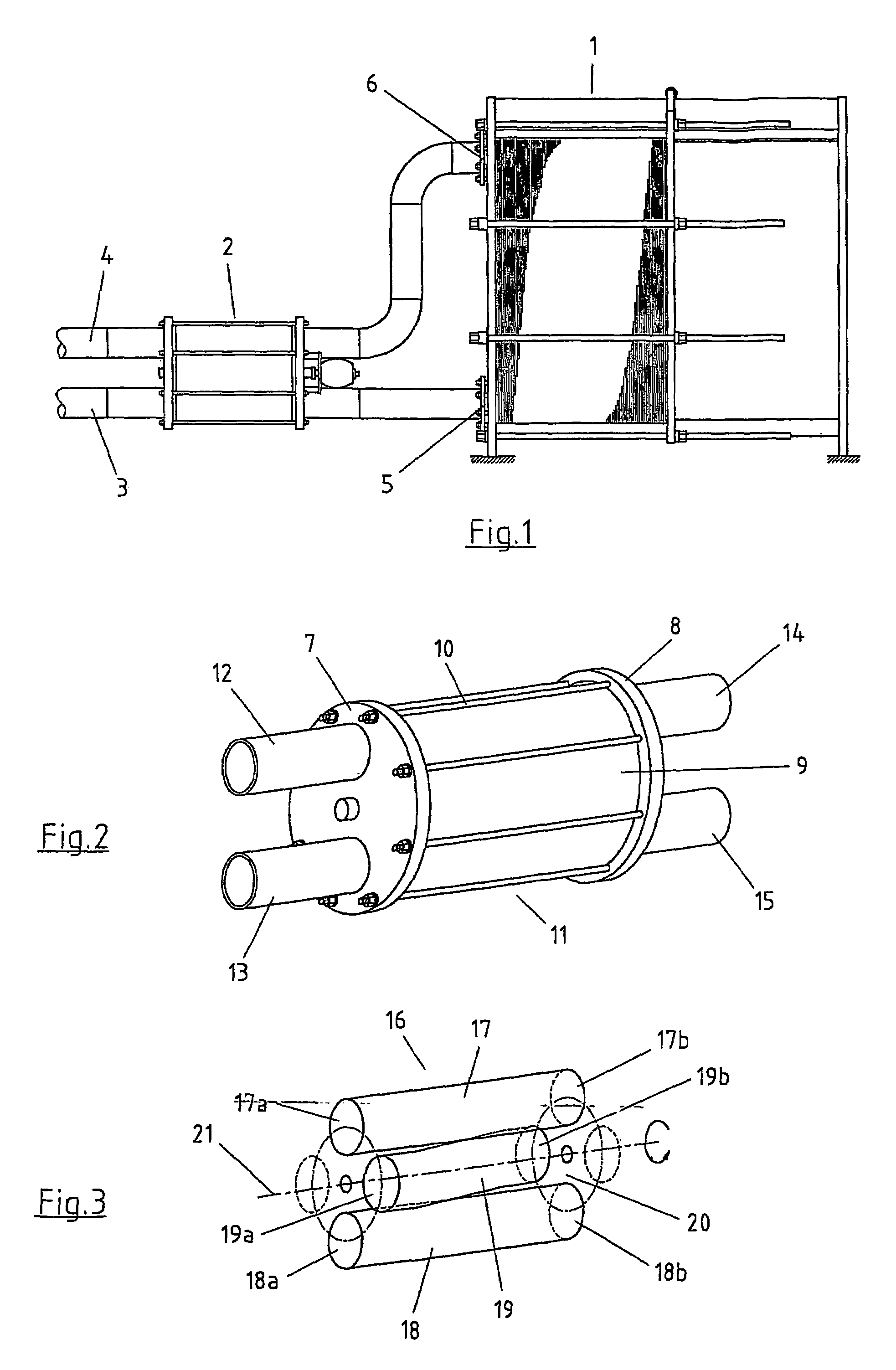
[0023]In FIG. 1 a plate heat exchanger 1 and a back flushing valve 2 being mounted on an inlet and outlet conduit 3 and 4, respectively, is shown. During normal operation the valve body of the back flushing valve is suitably rotated into a first position such that the inlet conduit 3 is connected with the port 5 of the heat exchanger and the outlet conduit 4 with the port 6, via two flow passages in the valve body. During normal operation the port 5 is an inlet port and the port 6 is an outlet port.

[0024]During back flushing the valve body is rotated into a second position such that the inlet pipe 3 becomes connected with the port 6, and the outlet pipe 4 with the port 5, which means that the port 6 becomes the inlet port and the port 5 becomes the outlet port. The construction and the function of the back flushing valve is described in greater detail in connection to FIGS. 2–13.

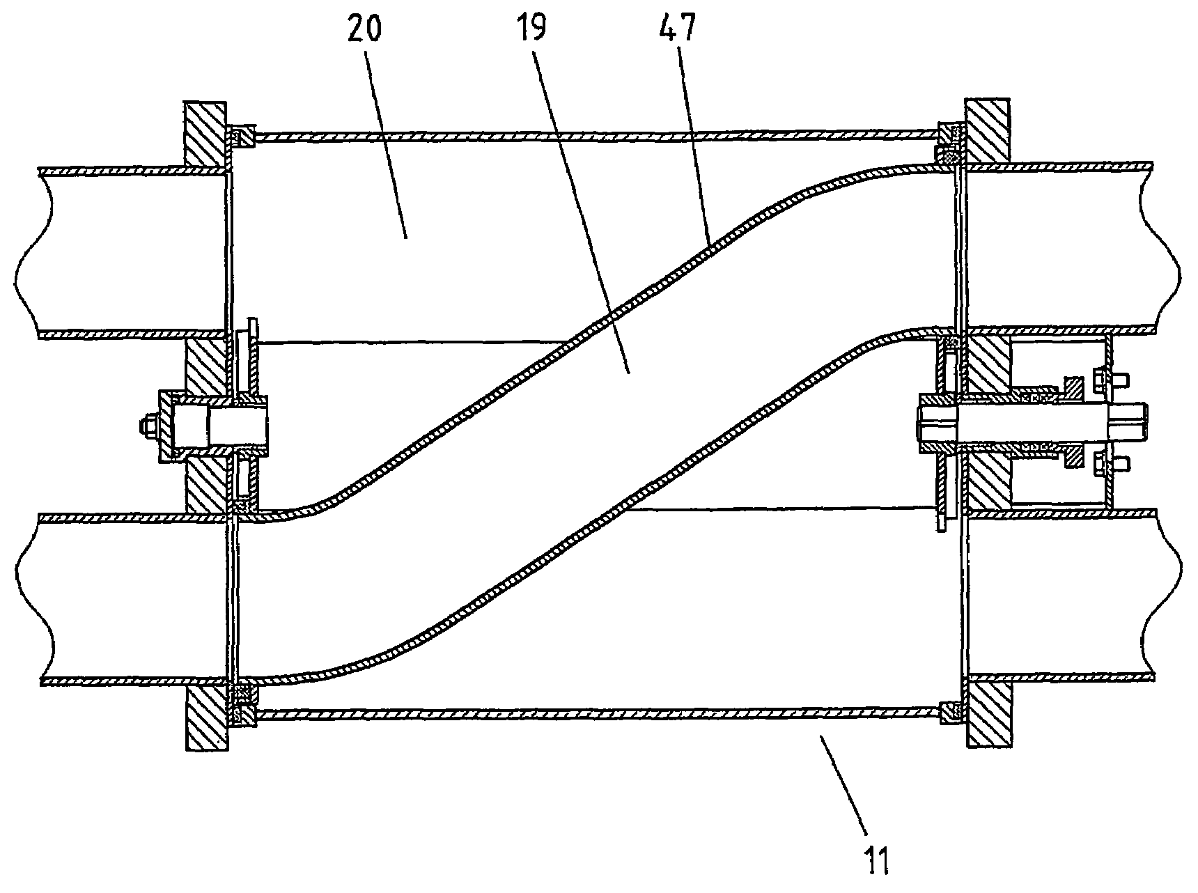
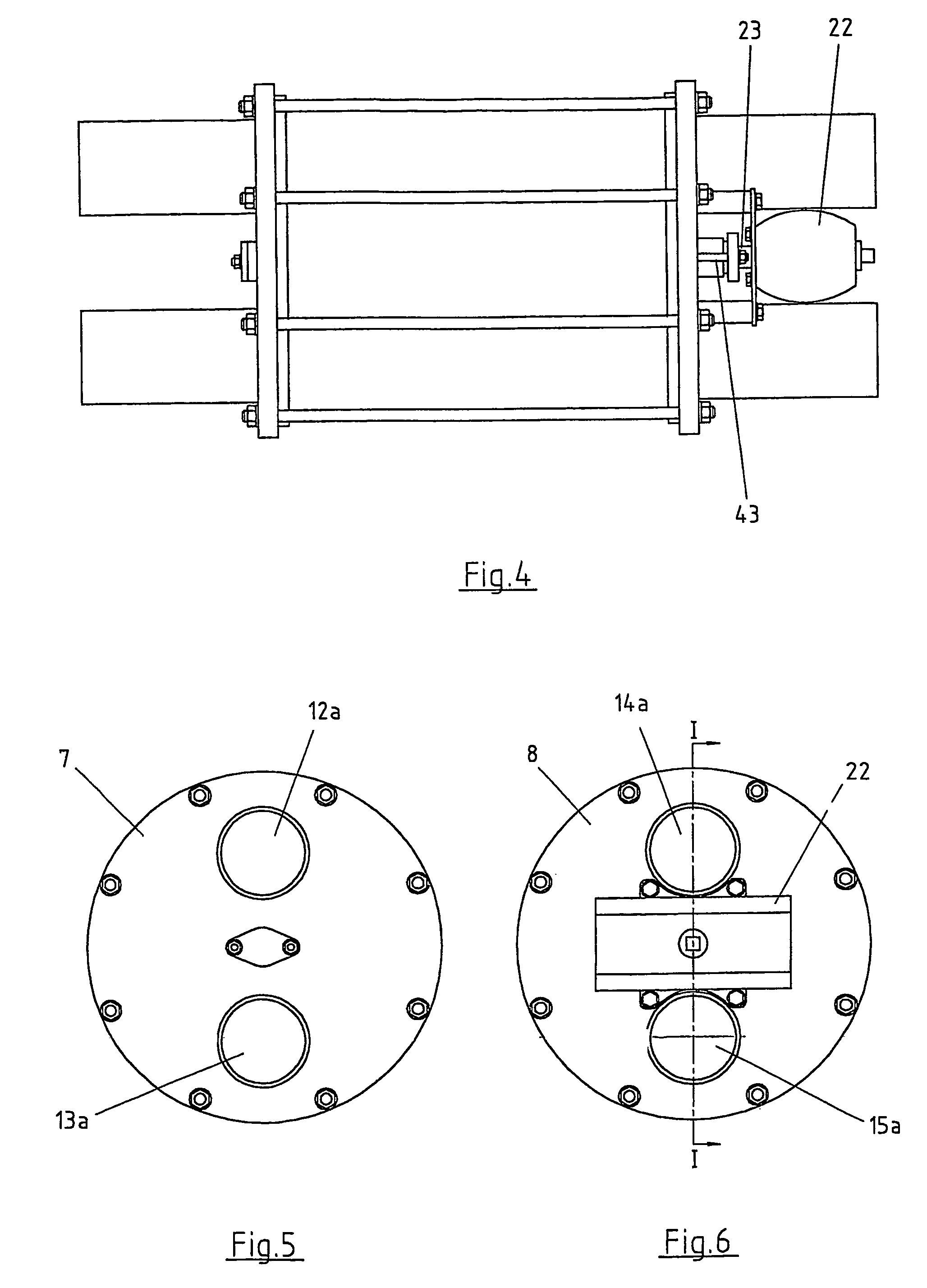
[0025]In FIG. 2 the back flushing valve is shown in an inclined projection. The valve house 11 consists o...


PUM


Abstract

A valve and use of a valve. The valve changes the direction of flow of a fluid in pipings conducting the fluid to and from a heat exchanger. A cylindrical casing and a valve body enclosed therein can be rotated between two positions. The valve body has three flow passages. A fourth flow passage is constituted by the space between the house of the valve and respective walls around the flow passages in the valve body. The entire valve is flushed by the fluid during operation, thereby eliminating the risk for accumulation of dirt in the valve.

Description

BACKGROUND OF THE INVENTION[0001]The present invention relates to a valve for changing the direction of flow of a fluid in pipe conduits conducting the fluid to and from a heat exchanger, respectively, said valve comprising a rotateable valve body and an enclosing valve house consisting of a cylindrical casing with end plates, wherein said valve body is rotatable around a rotary axis coinciding with a thought centre line of the cylindrical casing, and four flow passages extending through the valve house and being oriented in such a way that two diametrically located flow passages are approximately parallel with the rotary axis of the valve body and that the two other flow passages extend obliquely through the valve house, and, when the valve body is rotated into a first position, the flow passages connect a first connection port in the first end plate with a first connection port in the second end plate, and a second connection port in the first end plate with a second connection po...

Claims


Application Information

Patent Timeline
IPC IPC(8): F16K11/074F28F27/02
CPCF16K11/074F28F27/02F28G9/00F28G13/00Y10T137/5689Y10T137/86839
Inventor BLOMGREN, RALF ERIK
Owner MARINNOVATION
Why Eureka
Try Eureka