
Vent head

a technology of steam system and vent head, which is applied in the direction of separation of dispersed particles, separation processes, transportation and packaging, etc., can solve the problems of time-consuming installation of known vent heads and inability to separate all of the water that is entrained in steam

Active Publication Date: 2011-12-29
SPIRAX SARGO LTD
View PDF1 Cites 0 Cited by
  • Summary
  • Abstract
  • Description
  • Claims
  • Application Information

AI Technical Summary

Benefits of technology

[0008]Aspects of the invention relate to vent heads and related methods that improve the separation of entrained water from steam and / or is less complicated to install.

Problems solved by technology

Whilst such a vent head is suitable for some applications, there are a number of drawbacks associated with it.
For example, it is not capable of separating all of the water that is entrained in the steam.
Further, known vent heads can be time consuming to install due to the pipework connections that are necessary.

Method used


Image

  • Vent head
  • Vent head
  • Vent head

Examples


Embodiment Construction

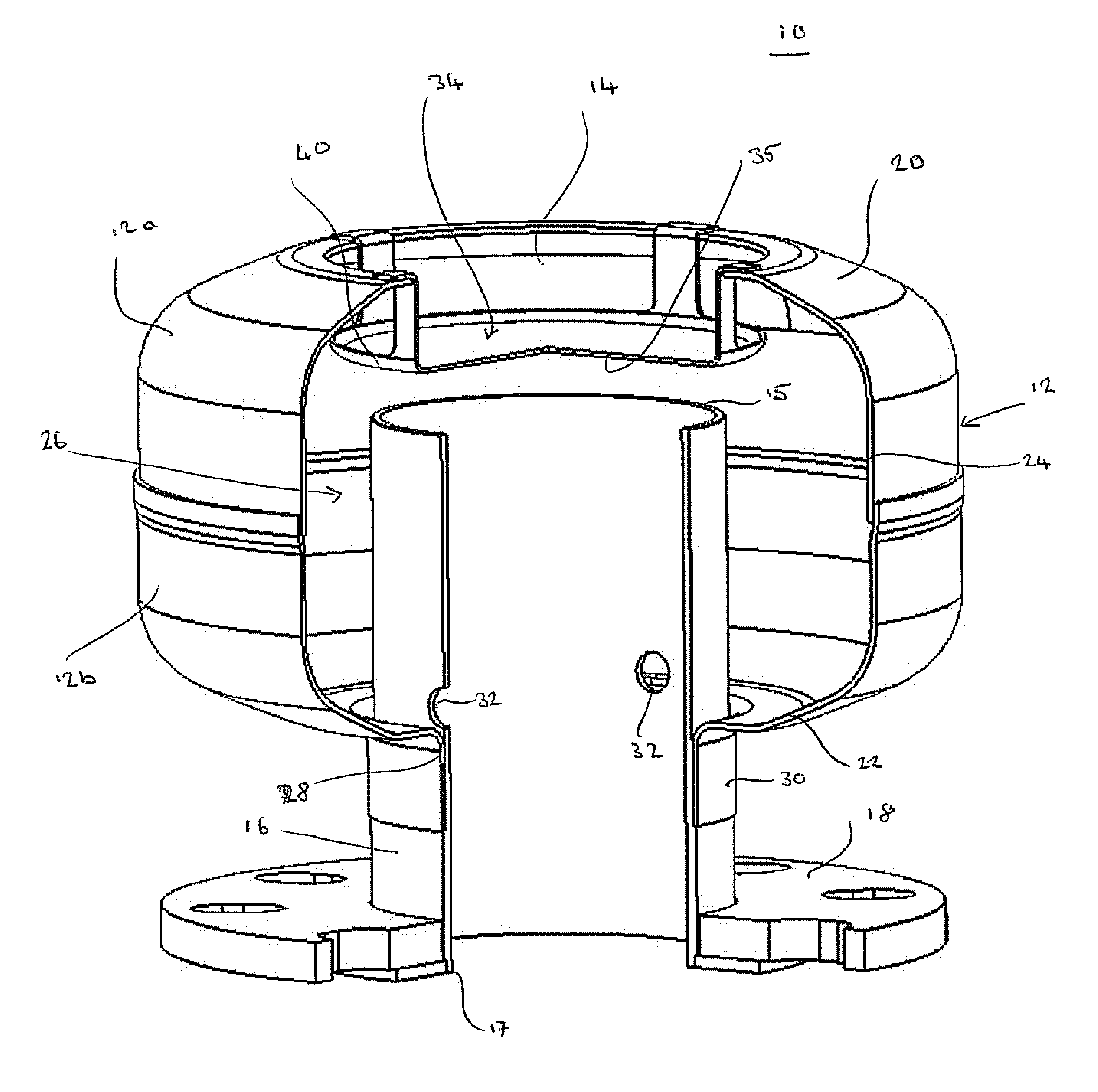
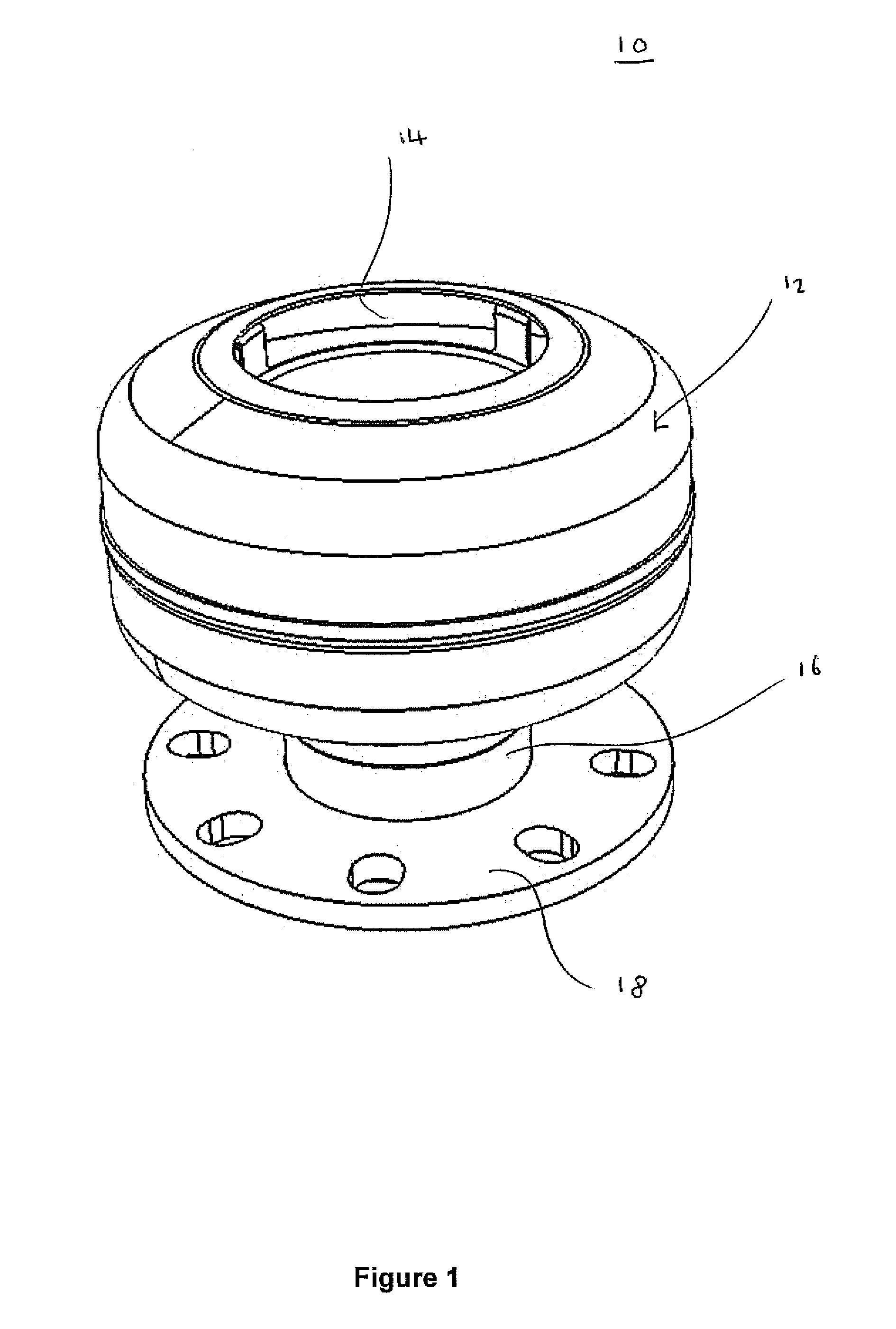
[0025]As shown in FIG. 1, the vent head 10 may comprise a body 12 that is provided with a vent head outlet 14, and a steam inlet pipe (or conduit) 16. The steam inlet pipe 16 is provided with a flange 18 that can be used to attach the vent head 10 to an open-ended steam vent pipe that supplies steam that is to be discharged, or vented, to the atmosphere.

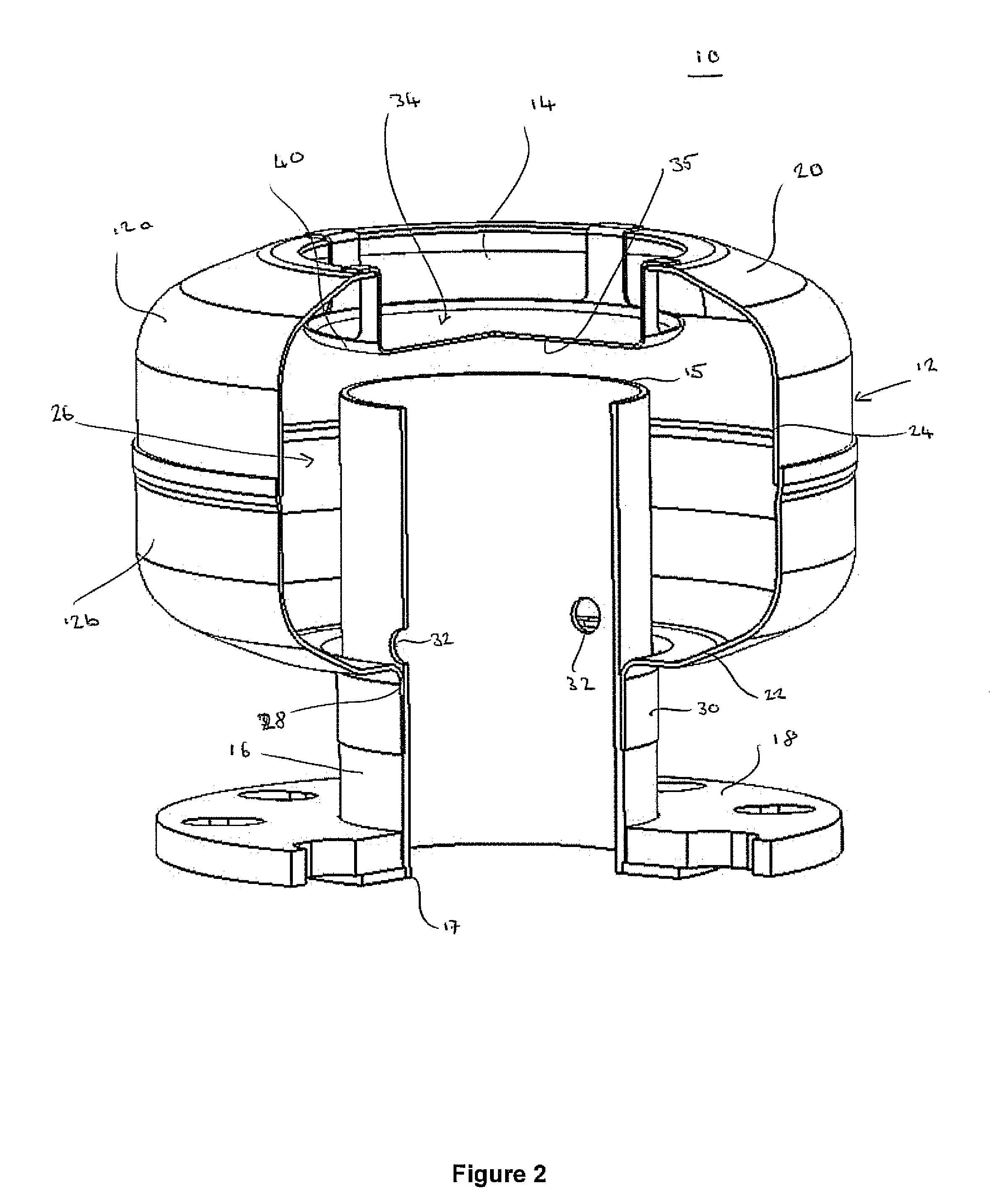
[0026]With reference to FIGS. 2 and 3, the body 12 of the vent head 10 comprises a top wall 20, a bottom wall 22, and an annular side wall 24 and therefore the body 12 is substantially cylindrical. The body 12 is made from a first upper part 12a that comprises the top wall 20 and a portion of the annular side wall 24, and a second lower part 12b that comprises the bottom wall 22 and a portion of the annular side wall 24. The upper and lower parts 12a, 12b are fitted together to form the body 12. The body 12 defines a vent head chamber 26 which is the interior of the body 12.

[0027]A steam pipe opening 28 is provided in the bottom wall...


PUM

PropertyMeasurementUnit
radius of curvatureaaaaaaaaaa
horizontal lengthaaaaaaaaaa
temperatureaaaaaaaaaa

Abstract

A vent head for a steam system is provided. In one embodiment, the vent head may comprise a body defining a vent head chamber and having a vent head outlet. The vent head comprises a steam inlet conduit having a steam outlet that opens into the vent head chamber and a baffle disposed within the vent head chamber and above the steam outlet. The baffle may have an impingement region and a convex portion which is disposed between the impingement region and the edge of the baffle. In use, the steam outlet discharges steam into the vent head chamber which impinges on the impingement region of the baffle, thereby separating entrained liquid water from the steam.

Description

CROSS-REFERENCE TO RELATED APPLICATION[0001]The present application claims priority to GB 1010720.9 filed on 25 Jun. 2010 and GB 1010719.1 filed on 25 Jun. 2010, which are each hereby incorporated by reference in their entirety for any and all purposes.BACKGROUND[0002]Aspects of the present invention relates to a vent head for a steam system.[0003]In an industrial and heating process utilizing steam, steam is generated in a boiler and transferred through pipework at high temperature and pressure to various industrial processes where the energy in the steam is utilised.[0004]Some steam system components, such as blow down vessels, include open-ended steam vent pipes that are used to vent steam to the atmosphere. It is known to provide the steam vent pipes with a vent head in order to safely discharge steam to the atmosphere at a low velocity.[0005]One type of known vent head comprises a housing containing a baffle which is arranged to intercept steam entering the housing. The baffle ...

Claims


Application Information

Patent Timeline
Patent Type & Authority Applications(United States)
IPC IPC(8): B01D45/08
CPCB01D45/08Y10T137/8593
Inventor VIVIAN, TOMROSAGRO, JOE
Owner SPIRAX SARGO LTD
Learn More