Method and System for Detection of a Circuit Board to be Installed in an Apparatus and Apparatus

a circuit board and installation method technology, applied in the field of method and system for detection of circuit boards, can solve the problems of false increase production costs, delay the product delivery to the customer, etc., and achieve the effect of facilitating precise interconnection of circuit boards and increasing production costs

Inactive Publication Date: 2015-04-23
ABB OY
View PDF4 Cites 1 Cited by
  • Summary
  • Abstract
  • Description
  • Claims
  • Application Information

AI Technical Summary

Benefits of technology

[0011]To avoid interconnection of two circuit boards, which should not be interconnected, therefore elaborate installation of the circuit boards is necessary. The interconnecting cables can be coloured or otherwise marked and may be of a predetermined length to facilitate precise interconnection of the circuit boards. Nevertheless false interconnection of circuit boards takes place during production of apparatuses. Fault detection and correction of defects increase production costs and may delay the product delivery to the customer.
[0012]The embodiments of the present invention are based on the object to ensure installation of a required circuit board in a corresponding housing in an apparatus. An unintentional installation of a circuit board in a housing, which is not required to be installed in the housing, should be avoided. The embodiments of the invention are particularly useful in production of apparatuses such as electric drive systems with a plurality of circuit boards. The circuit boards can be installed in the corresponding housings without unintentionally interconnecting circuit boards which should not be interconnected. Another object of the embodiments of the present invention is to provide a method and a system for detection of a circuit board to be installed in an apparatus such as an electric drive, wherein installation of the required circuit board is ensured.

Problems solved by technology

This may especially happen when one of the circuit boards installed in the apparatus is not of the type required or of the wrong configuration.
Nevertheless false interconnection of circuit boards takes place during production of apparatuses.
Fault detection and correction of defects increase production costs and may delay the product delivery to the customer.

Method used


Image

  • Method and System for Detection of a Circuit Board to be Installed in an Apparatus and Apparatus
  • Method and System for Detection of a Circuit Board to be Installed in an Apparatus and Apparatus
  • Method and System for Detection of a Circuit Board to be Installed in an Apparatus and Apparatus

Examples


first embodiment

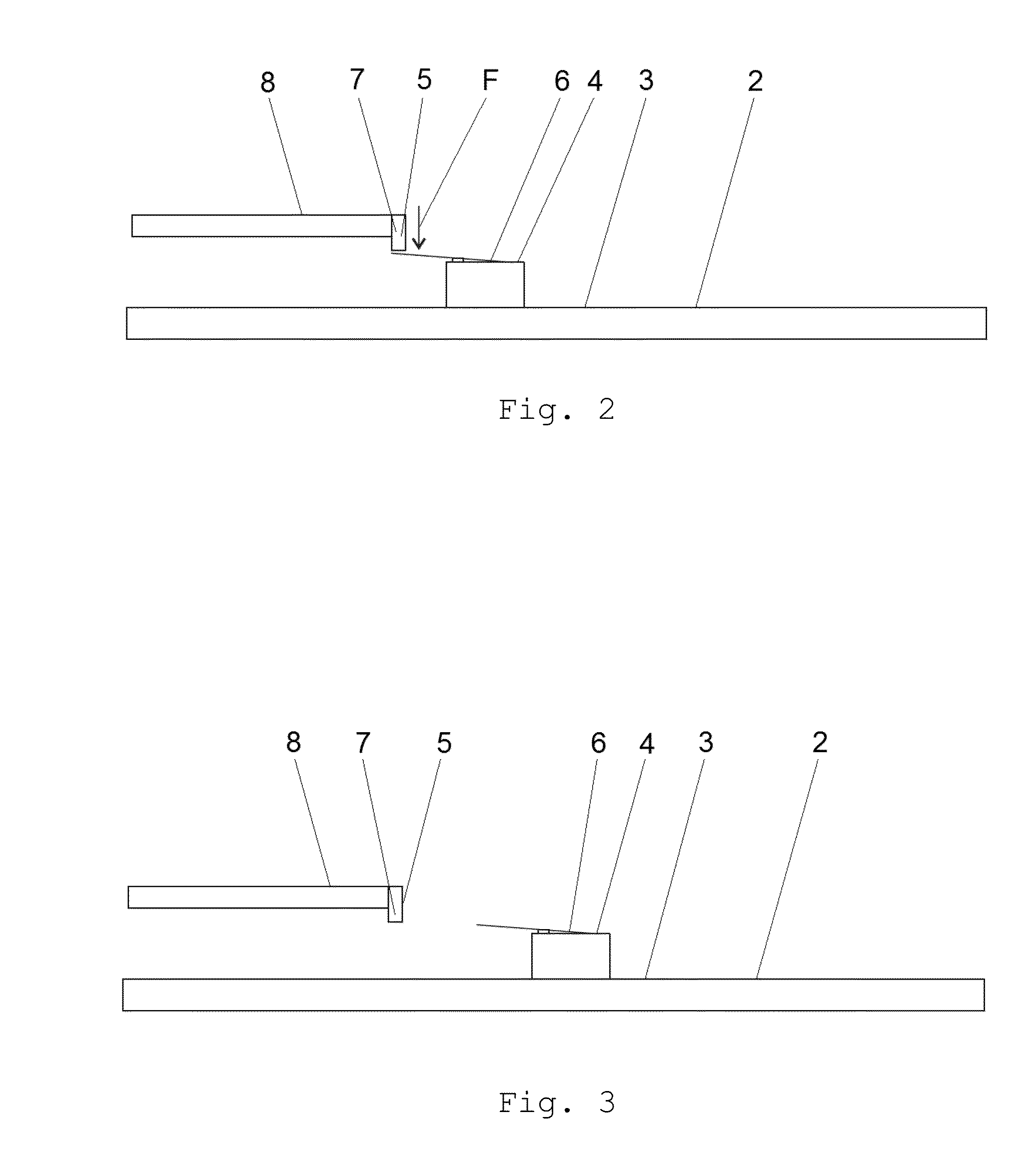
[0052]In FIG. 2 a schematic view of the invention is shown. At least one microswitch element 6, i.e. a first element 4, is fixedly arranged at a defined position on the surface 3 of a circuit board 2. In a corresponding housing 8 of the circuit board 2 at least one pen-like element or protrusion 7, i.e. a second element 5, is fixedly arranged at a defined position. During installation of a required circuit board 2 in the housing 8 of the circuit board 2 the microswitch element 6 arranged on the circuit board 2 is brought into contact with the pen-like element or protrusion 7 arranged in the housing 8 of the circuit board 2. The pen-like element or protrusion 7 exerts a mechanical force and closes the at least one microswitch element 6. When the microswitch element 6 is closed a signal is generated that the required circuit board 2 has been detected. The installation position of the required circuit board 2 then coincides with the predetermined mounting position.

[0053]Information inc...

second embodiment

[0057]FIG. 4 shows a schematic view of the invention. A jump wire element 9, i.e. a first element 4, is fixedly arranged at a defined position on the surface 3 of a circuit board 2. In a corresponding housing 8 of the circuit board 2 a jump wire element 7, i.e. a second element 5, is fixedly arranged at a defined position. During installation of the required circuit board in the housing 8 of the circuit board 2 the jump wire element 9 arranged on the circuit board 2 is brought into contact with the jump wire element 9 arranged in the housing 8 of the circuit board 2. The jump wire element 9 arranged in the housing 8 can close an electric circuit and then the circuit board 2 can detect if there is an interconnection between the jump wire element 9 arranged on the surface 3 of the circuit board 2 and the jump wire element 9 arranged in the housing 8 or not. When the electric circuit is closed an expected signal is generated that the required circuit board 2 has been detected. The inst...

third embodiment

[0059]In FIG. 6 a schematic view of the invention is illustrated. Two detecting contact elements 10 are fixedly arranged at a defined position on the surface 3 of a circuit board 2. The two detecting contact elements 10 may be for example made of copper. In a corresponding housing 8 of the circuit board 2 a conducting element 11 is fixedly arranged at a defined position. The conducting element 11 is made of conductive material and may be preferably formed bow-like. During installation of the required circuit board 2 in the housing 8 of the circuit board 2 the two detecting contact elements 10 arranged on the circuit board 2 are brought into contact with the conducting element 11 arranged in the housing 2 of the circuit board 2. The conducting element 11 interconnects the detecting contact elements 10. When detecting contact elements 10 are interconnected, a signal is generated that the required circuit board 2 has been detected. The installation position of the required circuit boar...


PUM


Abstract

The present invention concerns a method and system for detection of a circuit board to be installed in an apparatus such as an electric drive. At least one first element is fixedly arranged at at least one defined position on the surface of the circuit board and at least one second element is fixedly arranged at at least one defined position in a housing of the circuit board. The at least one first element interacts with the at least one second element during installation of the required circuit board. A matching signal or decoding signal is generated when the first element and the second element interact. The invention further concerns an apparatus such as an electric drive with at least one circuit board arranged in a housing.

Description

TECHNICAL FIELD OF THE INVENTION[0001]The present invention relates to a method and system for detection of a circuit board to be installed in an apparatus such as an electric drive. The invention further relates to an apparatus such as an electric drive with at least one circuit board installed in a housing.BACKGROUND OF THE INVENTION[0002]US 2006 / 0094295 A1 teaches that an apparatus of large scale such as a router, a communication control unit, or a plant control unit has a plurality of printed circuit boards. These printed circuit boards have inventory information including, for example, a manufacturing date, a manufacturing serial number, a drawing number, a version number, a name, a date of mounting, a final maintenance date or an actual mounting position showing the mounting position on the apparatus of the printed circuit board. Such inventory information is referred to and confirmed when managing the stock of printed circuit boards, mounting the printed circuit board on an a...

Claims


Application Information

Patent Timeline
Patent Type & Authority Applications(United States)
IPC IPC(8): G06Q10/08
CPCG06Q10/087H05K7/1455
Inventor HELLMAN, JOUKO TOPIASNIEMI, MIKA
Owner ABB OY
Why Eureka
Try Eureka