Combustion pressure sensor designed to ensure stability of output characteristic and sensitivity

a technology of combustion pressure sensor and output characteristic, which is applied in the direction of fluid pressure measurement, machines/engines, instruments, etc., can solve the problems of increasing the production cost of combustion pressure sensors, physical damage to the joints of the sensors, and the breakage of the center shaft b>, so as to increase the signal-to-noise ratio of output

Active Publication Date: 2005-12-13
DENSO CORP
View PDF19 Cites 55 Cited by
  • Summary
  • Abstract
  • Description
  • Claims
  • Application Information

AI Technical Summary

Benefits of technology

[0011]It is another object of the invention to provide a combustion pressure sensor designed to minimize a unit-to-unit variation in sensitivity of combustion pressure sensors and ensure the stability of output characteristics thereof.
[0013]Specifically, the combustion pressure sensor is designed to apply the physical load to the sensing element which arises from the bend deformation of the bendable member, thus eliminating the need for a surface-to-surface contact between the sensing element and the bendable member. This results in a decreased unit-to-unit variation in sensitivity of combustion pressure sensors and ensures the stability of output characteristics of the combustion pressure sensor.
[0017]The combustion pressure sensor may also include a voltage adjuster working to adjust a level of the voltage signal provided by the voltage converter in order to increase a signal-to-noise (S / N) ratio. Piezoelectric devices, as used in measuring the combustion pressure of automotive engines, are usually designed to produce a charge of several pc to several hundreds pc per applied pressure of 1 Mpa. The charge is, thus, exposed to electric noises arising from accessories or a radio set during transmission to an engine ECU. Additionally, due to a variation in parts dimension or assembling errors, typical combustion pressure sensors have the problem that sensor outputs differ from each other when a combustion pressure is 1 Mpa. This results in complex engine control or decreased accuracy of the engine control or requires an additional sensor for correcting an output of the combustion pressure sensors, thus lading to increased production costs of the combustion pressure sensors.
[0020]According to the second aspect of the invention, there is provided a method for adjusting an output of a pressure combustion sensor which includes a piezoelectric device sensitive to a physical load arising from a combustion pressure in a combustion chamber of an internal combustion engine to produce a charge as a function of the physical load, a voltage converter working to convert the charge produced by the piezoelectric device into a voltage signal, and a voltage adjuster working to adjust a level of the voltage signal provided by the voltage converter. The method comprises: applying a physical load equivalent to the combustion pressure to the pressure combustion sensor; monitoring an output of the voltage adjuster; and adjusting a circuit constant of the voltage adjuster so as to bring the monitored output of the voltage adjuster into agreement with a desired one. This results in an increased signal-to-noise ratio of the output of the piezoelectric device.

Problems solved by technology

The application of a preload of as much as 3000N, however, results in breakage of the center shaft 111, etc. or physical damage to joints in the sensor.
This requires a high degree of machining accuracy, thus resulting in increased production costs of the combustion pressure sensors.

Method used


Image

  • Combustion pressure sensor designed to ensure stability of output characteristic and sensitivity
  • Combustion pressure sensor designed to ensure stability of output characteristic and sensitivity
  • Combustion pressure sensor designed to ensure stability of output characteristic and sensitivity

Examples


first embodiment

[0073]The structure of the combustion pressure sensor 1 of this embodiment produces the same beneficial effects as those in the

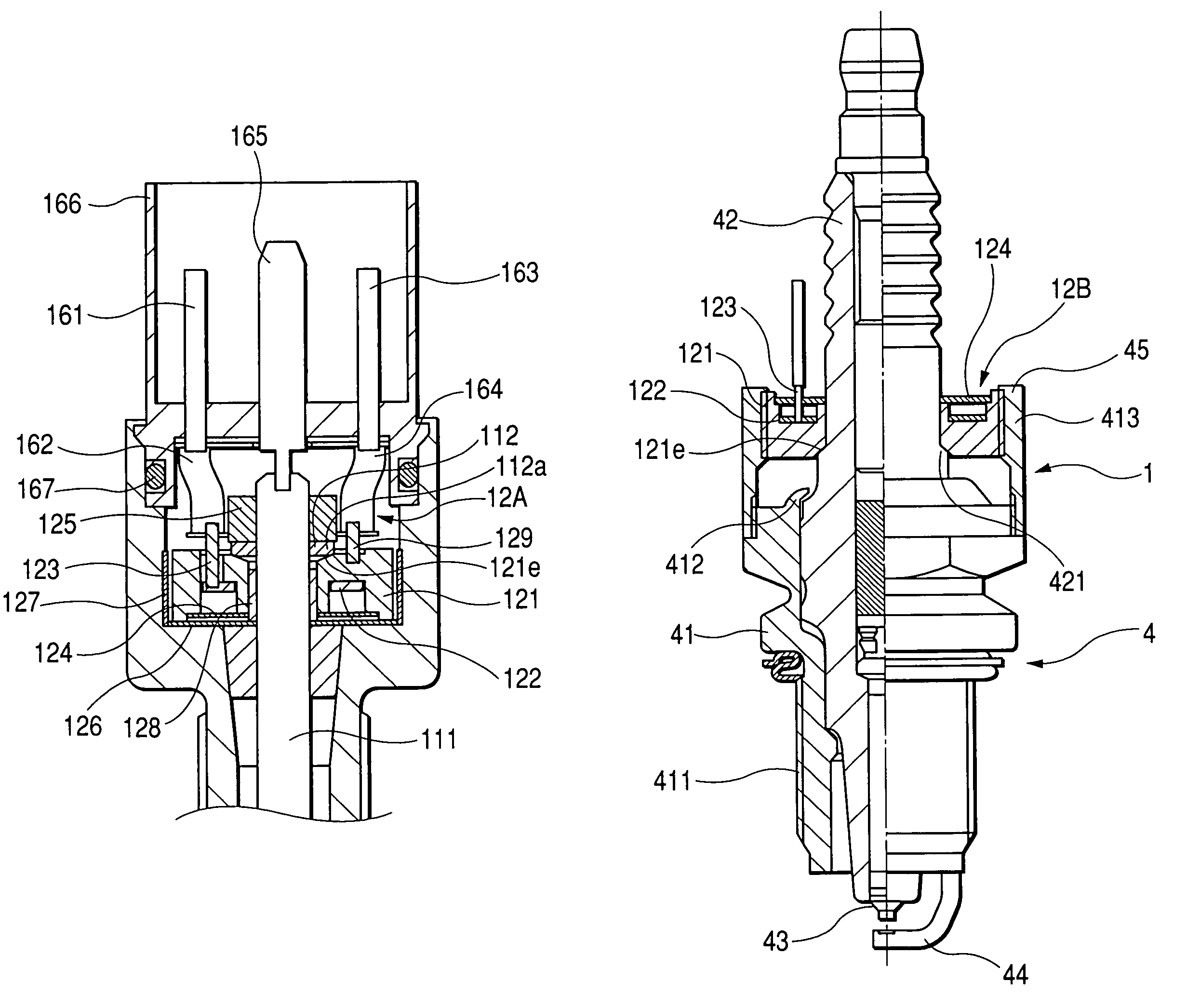
[0074]FIGS. 4 and 5 show the combustion pressure sensor 1 according to the third embodiment of the invention which is different from the second embodiment in structure of a load detector 12A and mounting structure for the load detector 12A. The same reference numbers as employed in FIG. 3 will refer to the same or similar parts, and explanation thereof in detail will be omitted here.

[0075]The load detector 12A includes the bendable member 121 which does not have the external thread 121a, as used in the first and second embodiments. The bendable member 121 is attached firmly to the housing 10 and the center shaft 111 through a lock nut 125.

second embodiment

[0076]A resinous insulating sheet 126 is disposed on the bottom surface of the bendable member 121. A resinous insulating wall 127 is disposed around the circumference of the bendable member 121. This insulates the bendable member 121 electrically from the housing 10. Further, a rubber tube 128 is fitted on an inner wall of the bendable member 121 to insulate the bendable member 121 electrically from the center shaft 111. The structure of this embodiment serves to facilitate ease of electrical insulation of the bendable member 121 from the housing 10 as compared with the second embodiment in which the bendable member 121 is fitted within the housing 10 using the internal thread 121a.

[0077]The lock nut 125 and the piston 112 are located farther from the combustion chamber 3 than the bendable member 121. The bendable member 121 has the tapered wall 121e formed on a surface thereof opposite a surface facing the combustion chamber 3. The tapered wall 121e is in line-to-line contact wit...

fourth embodiment

[0094]A hollow cylindrical separate casing 45 is, unlike the fourth embodiment, installed on the metal shell 41. Specifically, the casing 45 is screwed on the metal shell 41 to define a chamber within which the load detector 12B is disposed firmly. The use of the separate casing 45 results in simplicity of geometry of the metal shell 41, thus facilitating ease of machining of the metal shell 41 and crimping of the annular protrusion 412 to hold the porcelain 42 within the metal shell 41 before the casing 45 is installed on the metal shell 41.

[0095]FIG. 8 shows the combustion pressure sensor 1 according to the sixth embodiment of the invention which is a modification of the fifth embodiment, as illustrated in FIG. 7. The combustion pressure sensor 1 of this embodiment is different in structure of the bendable member 121 of the load detector 12C from that of the fifth embodiment. The same reference numbers as employed in the fourth embodiment will refer to the same parts, and explanat...


PUM

PropertyMeasurementUnit
combustion pressureaaaaaaaaaa
voltageaaaaaaaaaa
lengthaaaaaaaaaa

Abstract

A combustion pressure sensor for an internal combustion engine is provided. The sensor includes a sensing element such as a piezoelectric device sensitive to a physical load applied thereto to produce an electric signal indicative thereof and a bendable member. The bendable member is bent upon application of the combustion pressure in the engine to apply the physical load to the sensing element. Specifically, the physical load is applied to the sensing element which arises from the bend deformation of the bendable member, thus eliminating the need for a complete surface-to-surface contact between the sensing element and the bendable member. This results in a decreased unit-to-unit variation in sensitivity of combustion pressure sensors and ensures the stability of output characteristics of the combustion pressure sensor.

Description

BACKGROUND OF THE INVENTION[0001]1. Technical Field of the Invention[0002]The present invention relates generally to an improved structure of a combustion pressure sensor for measuring the combustion pressure of an internal combustion engine, and more particularly to such a combustion pressure sensor designed to ensure the stability of output characteristics and sensitivity thereof.[0003]2. Background Art[0004]FIG. 19 shows one of typical combustion pressure sensors, as taught in Japanese Patent First Publication No. 2002-327919.[0005]The combustion pressure sensor consists of a hollow cylindrical housing 10, a load detector 12, and a center shaft 111. The housing 10 is installed in a cylinder head of an internal combustion engine. The load detector 12 is sensitive to a physical pressure load to produce an electric signal indicative thereof. The center shaft 111 is disposed within the housing 10 and works to transmit the combustion pressure in the combustion chamber of the engine to...

Claims


Application Information

Patent Timeline
Patent Type & Authority Patents(United States)
IPC IPC(8): F02B77/08
CPCF02B77/08G01L23/222G01L27/00F23Q2007/002
Inventor WATARAI, TAKEHIRONAKASHIMA, FUMINORIHIRAMATSU, HIROMI
Owner DENSO CORP
Why Eureka
Try Eureka