Power converter and operating method thereof

a power converter and operating method technology, applied in the direction of dc-dc conversion, power conversion systems, instruments, etc., can solve the problems of reducing the period of pwm signal, affecting the voltage conversion efficiency of the power converter, and the output voltage generated by the power converter fails to reach the expected output voltage, so as to achieve the effect of avoiding the drawback ensuring the stability of the output voltage of the power converter

Active Publication Date: 2015-09-29
UPI SEMICON CORP
View PDF12 Cites 0 Cited by
  • Summary
  • Abstract
  • Description
  • Claims
  • Application Information

AI Technical Summary

Benefits of technology

[0012]In an embodiment, when the input voltage is decreased but not lower than the default voltage, the PWM unit keeps the period of the PWM signal unchanged and increase the on-time of the switch conducting signal.
[0015]Compared to the prior arts, when the input voltage is decreased to be lower than the default voltage, the power converter of the invention can increase the period of the PWM signal with the decreasing of the input voltage. Therefore, the on-time (Ton) provided by the switch conducting signal can be large enough for the output stage to generate expected output voltage to effectively avoid the drawback of the output voltage of the power converter decreased with the decreasing of the input voltage in the prior arts, and the stability of the output voltage of the power converter can be ensured.

Problems solved by technology

However, because the input voltage is often decreased with time, the output voltage generated by the power converter fails to reach the expected output voltage.
It seriously affects the voltage conversion efficiency of the power converter 1.

Method used


Image

  • Power converter and operating method thereof
  • Power converter and operating method thereof
  • Power converter and operating method thereof

Examples


Embodiment Construction

[0024]A preferred embodiment of the invention is a power converter. In fact, the power converter of the invention can be applied to a fixed frequency DC-DC converter, but not limited to this. The invention can be also applied to a constant-on-time (COT) DC-DC converter.

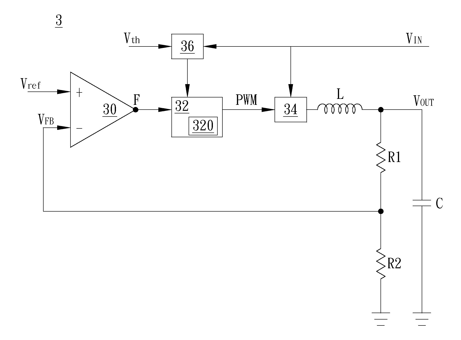
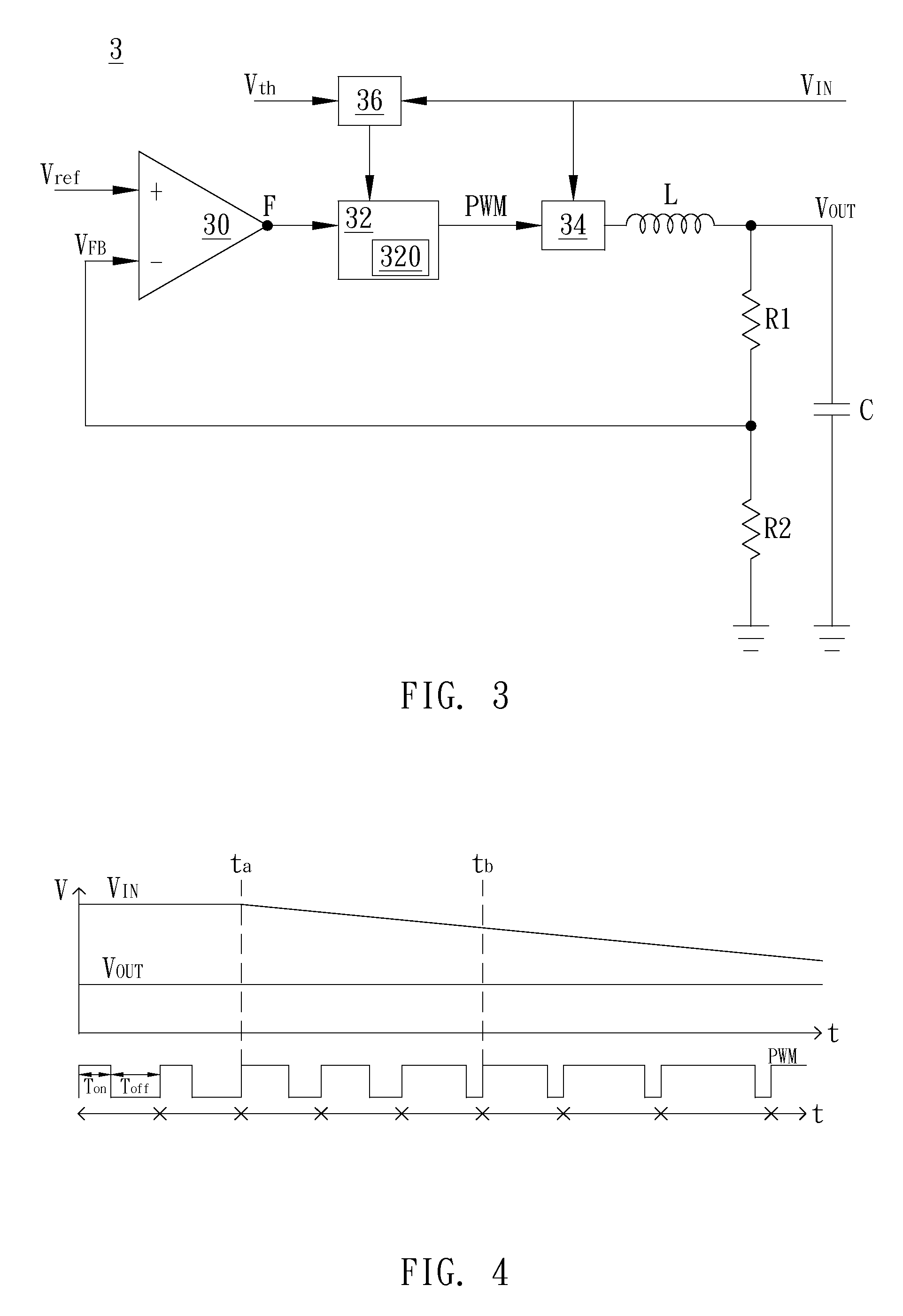
[0025]Please refer to FIG. 3. FIG. 3 illustrates a schematic diagram of the circuit structure of a power converter in this embodiment. As shown in FIG. 3, the power converter 3 includes an output stage 34, an amplifier unit 30, an input voltage detecting unit 36, and a PWM unit 32. The output stage 34 is coupled between an input terminal and a ground terminal, and the output stage 34 is coupled to the PWM unit 32 and an output inductor L; the input voltage detecting unit 36 is coupled to the input terminal and the PWM unit 32; the PWM unit 32 is coupled to the amplifier unit 30, the output stage 34, and the input voltage detecting unit 36; the amplifier unit 30 is coupled to the output stage 34, the PWM unit 32, a fir...


PUM


Abstract

A power converter and an operating method therefore are disclosed. The power converter includes an output stage, an input voltage detecting unit, and a pulse width modulation (PWM) unit. The output stage is coupled between an input terminal and a ground terminal. The input voltage detecting unit is used to detect an input voltage. The PWM unit is coupled to the output stage and the input voltage detecting unit and used to provide a PWM signal to the output stage. The PWM unit adjusts an on-time of a switch conducting signal of the PWM signal according to the input voltage and a default voltage. When the input voltage is lower than the default voltage, the PWM unit increases the on-time of the switch conducting signal and a period of the PWM signal.

Description

BACKGROUND OF THE INVENTION[0001]1. Field of the Invention[0002]The invention relates to a DC-DC converter; in particular, to a power converter capable of converting the decreased input voltages into expected output voltages and an operating method thereof.[0003]2. Description of the Prior Art[0004]In general, an input voltage inputted to a power converter should be certain extent higher than an expected output voltage to smoothly generate the expected output voltage. However, because the input voltage is often decreased with time, the output voltage generated by the power converter fails to reach the expected output voltage.[0005]As shown in FIG. 1, under the constant-on-time (COT) pulse width modulation (PWM) structure, an amplifier 10 of a power converter 1 receives a feedback voltage VFB (related to an output voltage) and a reference voltage Vref. Once the feedback voltage VFB is lower than the reference voltage Vref, it means that the output voltage VOUT generated by the power ...

Claims


Application Information

Patent Timeline
Patent Type & Authority Patents(United States)
IPC IPC(8): G05F1/67G05F5/00H02M3/155H02M1/00
CPCG05F5/00H02M3/155H02M2001/0022H02M1/0022
Inventor SHEN, CHIEN-YUAN
Owner UPI SEMICON CORP
Why Eureka
Try Eureka