System and method for diagnostic supervision of internet transmissions with quality of service control

a technology of diagnostic supervision and internet transmission, applied in the field of communication, can solve the problems of udp not providing error detection/correction, other quality of service (qos) within the existing protocol, information is not divided into packets, etc., and achieves the effect of enhancing the internet transmission properties of communication and generating a quality of service valu

Inactive Publication Date: 2006-10-10
CHEMTRON RES
View PDF6 Cites 70 Cited by
  • Summary
  • Abstract
  • Description
  • Claims
  • Application Information

AI Technical Summary

Benefits of technology

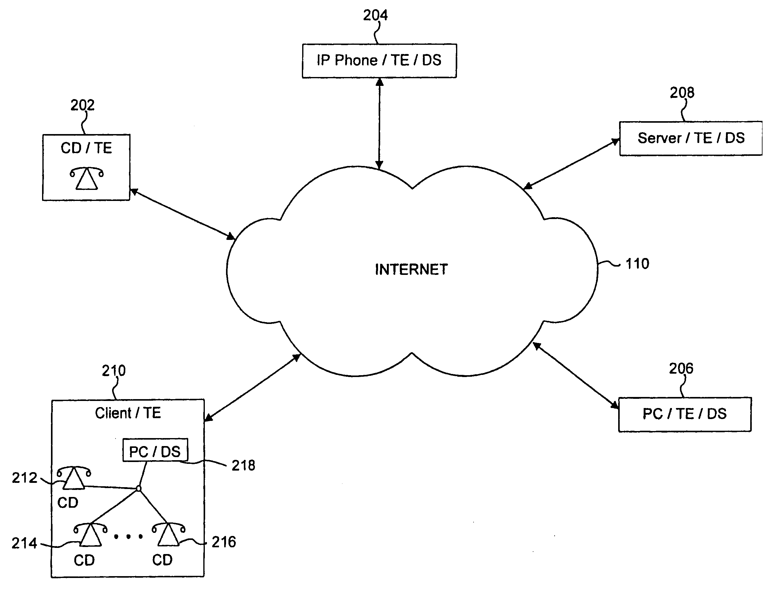
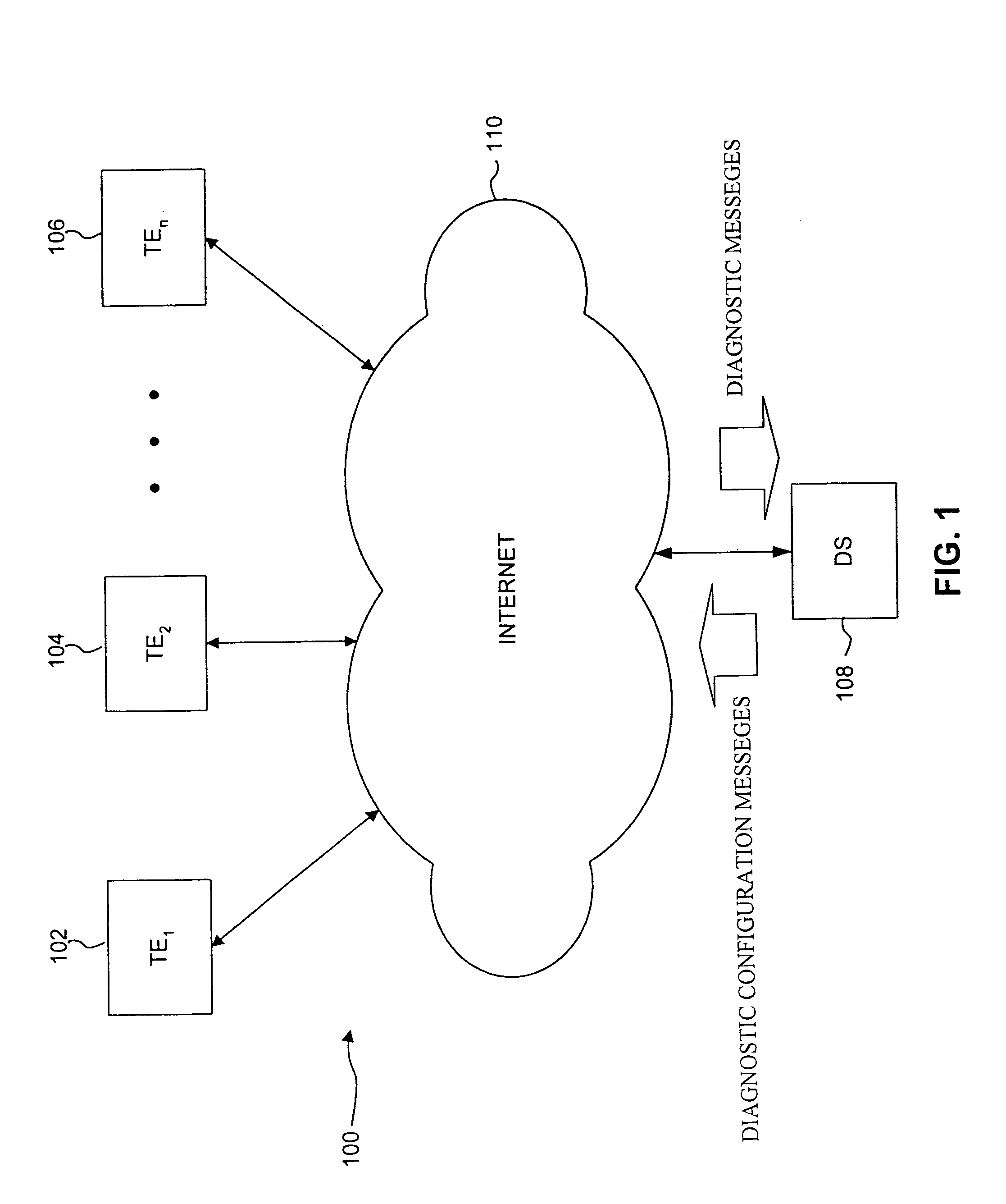
[0020]The flexibility afforded by the DCMs allows large amounts of customized diagnostic information to be delivered in a non-intrusive manner. This results from diagnostic information being transmitted when required. The DMs are transmitted by the TEs to the DS, for example. Alternatively, in a system with more that one DS, the TEs can transmit DMs to the plural DSs, other TEs or any network device.
[0022]In one embodiment of the present invention, the system can generate a quality of service value based on the diagnostic information provided by the DMs. The quality of service may then be used by the system to enhance the Internet transmission properties of the communication.

Problems solved by technology

This break down of information into packets is a result of a variety of reasons, including hardware limitations, for example.
As a result, related packets forming a package may well be sent along different routes, with different delays.
However, UDP does not provide for error detection / correction or any other quality of service (QoS) within the existing protocol.
Thus, the quality and transmission of calls is uncertain when using UDP.
As a result, the UDP protocol does not provide a guarantee that all of the packets for a particular message arrive.
This aspect of UDP makes UDP an unreliable transport mechanism.

Method used


Image

  • System and method for diagnostic supervision of internet transmissions with quality of service control
  • System and method for diagnostic supervision of internet transmissions with quality of service control
  • System and method for diagnostic supervision of internet transmissions with quality of service control

Examples


Embodiment Construction

I. Overview of the Technology

[0051]The following section is an overview of basic Internet-related concepts, as discussed in Pricewaterhouse Coopers® Technology Forecast: 1999 (Pricewaterhouse Coopers Technology Center, Menlo Park, Calif., 94025; order #TC-01-09).

[0052]Voice calls or facsimile transmissions, which are not distinguished from voice calls by the phone network, must first be converted from analog signals into digital form. This conversion is performed by a codec, i.e., a compression and decompression device. Codec devices convert analog voice to digital signals and digital signals back to analog, for example. A codec device may be implemented either in software or special-purpose hardware.

[0053]Digitally encoding of voice calls is also done in the PSTN for interoffice transmission by systems such as private branch exchanges (PBXs). However, the codecs used for VoIP use bandwidth more efficiently than the those used in the PSTN, carrying voice in as little as 5 Kbps compa...


PUM


Abstract

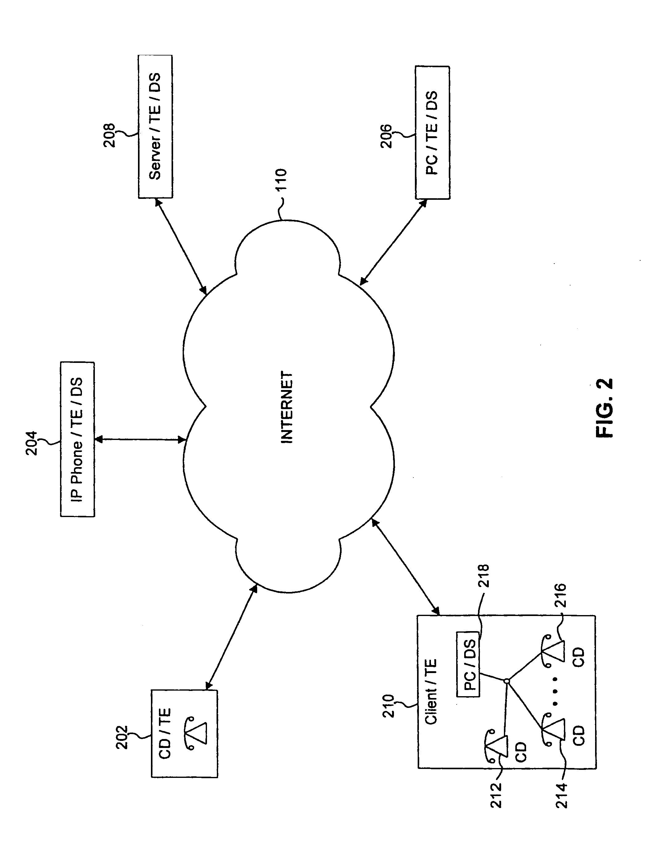
A system and method are provided for managing diagnostic and performance information for communications system terminal endpoints (TEs) communicating over an Internet Protocol (IP) network. The TEs communicate by transmissions that are voice, modem, facsimile, video, data transmissions, or the like. A Diagnostic Supervisor (DS) transmits Diagnostic Configuration Messages (DCMs) to the TEs. The TEs generate Diagnostic Messages (DMs) based on diagnostic information, including error statistics, voice statistics, facsimile statistics, video statistics, data statistics, or the like, concerning IP network transmissions in which the TEs participate. The DCMs instructs the TEs how to format and when to transmit DMs. The DMs are transmitted by the TEs to the DS. In a system with more than one DS, the TEs can transmit DMS to the plural DSs, other TEs or any network devices.

Description

[0001]This application is a Continuation-in-part Application of U.S. patent application Ser. No. 09 / 393,659, filed on Sep. 10, 1999 now U.S. Pat. No. 6,553,515, which is incorporated herein by reference in its entirety.BACKGROUND OF THE INVENTION[0002]1. Field of the Invention[0003]This invention generally relates to communications, and more specifically to a system and method for diagnostics supervision of Internet transmissions, such as VoIP calls.[0004]2. Related Art[0005]The uses of the public Internet are very diverse. A use that has recently gained much attention is Voice-over-Internet Protocol (VoIP) technology, which involves using the public Internet or a private IP network to carry voice calls, either partially or completely bypassing the public switched telephone network (PSTN).[0006]VoIP, as well as video conferencing, has been used by computer hobbyists to place no-charge, and typically low-quality, calls over the Internet, using microphones, video cameras, and speakers...

Claims


Application Information

Patent Timeline
Patent Type & Authority Patents(United States)
IPC IPC(8): H04L12/26H04L12/56H04L12/24
CPCH04L12/2602H04L41/5022H04L43/00H04L43/06H04L43/0829H04L43/0852H04L43/087H04L43/106H04L43/16
Inventor STARR, MICHAEL A.GROSS, CHARLES J.
Owner CHEMTRON RES
Why Eureka
Try Eureka