Spectrum spread communication synchronization establishing apparatus using frequency offset and receiver with the same

Active Publication Date: 2006-10-10
NEC CORP
View PDF25 Cites 6 Cited by
  • Summary
  • Abstract
  • Description
  • Claims
  • Application Information

AI Technical Summary

Benefits of technology

[0020]An object of the present invention is to provide means for setting a larger number of symbols to be in-phase added than a conventional example and enabling stable synchronization establishment even in the environment where the frequency offset or noises are mixed by using a synchronization establishing circuit in the spectrum spread communication receiver which has means for compensating for the phase rotation due to the frequency offset generated in the transmission path by the Doppler eff

Problems solved by technology

In addition, when the frequency offset increases, the sufficient gain cann

Method used


Image

  • Spectrum spread communication synchronization establishing apparatus using frequency offset and receiver with the same
  • Spectrum spread communication synchronization establishing apparatus using frequency offset and receiver with the same
  • Spectrum spread communication synchronization establishing apparatus using frequency offset and receiver with the same

Examples


second embodiment

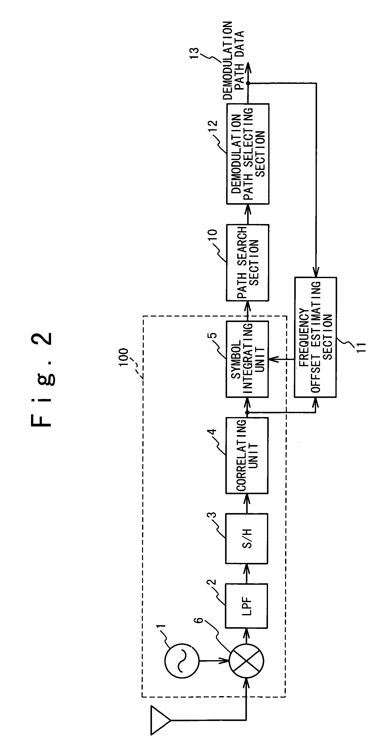
[0050]FIG. 3 is a block diagram showing the spectrum spread communication synchronization establishing circuit according to the present invention. The spectrum spread communication synchronization establishing circuit is composed of a plurality of synchronizing circuits 200 a plurality of path search sections 10, a frequency offset estimating section 11 and a demodulation path selecting section 12. Thus, the spectrum spread communication synchronization establishing circuit has the configuration to enable space diversity reception.

[0051]Each of the plurality of synchronizing circuits 200 is composed of a signal converting section of a local oscillator 1, a multiplier 6 and a low pass filter (LPF) 2, a sampling and holding circuit (S / H) 3, a correlating unit 4, and a symbol integrating unit 5 in the first embodiment. The basic synchronization establishing operation by the synchronizing circuit 200 in the second embodiment is same as that of the synchronizing circuit 100 in the first ...

third embodiment

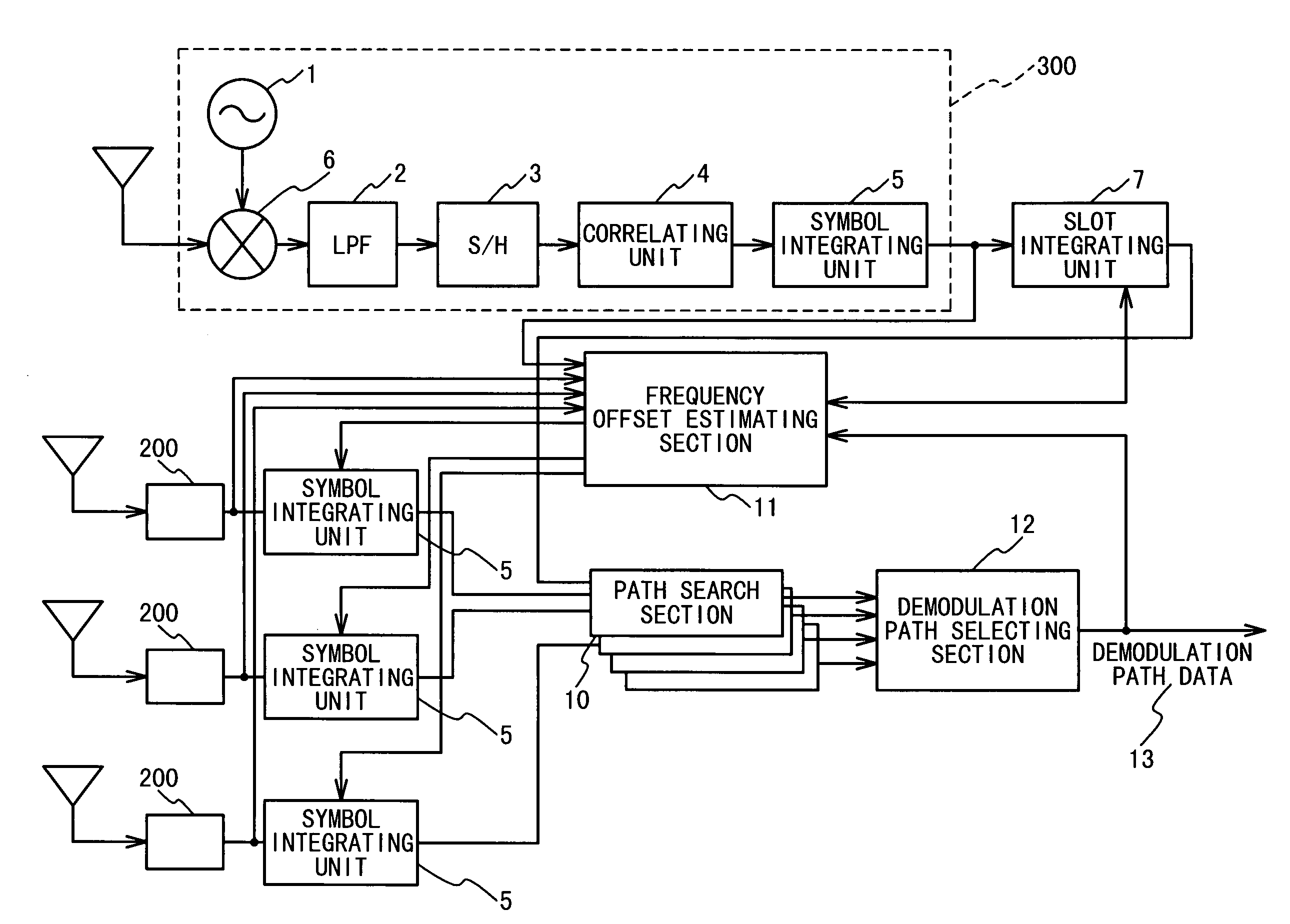
[0053]FIG. 4 is a block diagram showing the spectrum spread communication synchronization establishing circuit according to the present invention. In this embodiment, like the above embodiments, the spectrum spread communication synchronization establishing apparatus is composed of a plurality of synchronizing circuits 300, a plurality of slot integrating units 7, a plurality of path search sections 10, a frequency offset estimating section 11, and a demodulation path selecting section 12.

[0054]Each of the plurality of synchronizing circuits 300 is composed of a signal converting section of a local oscillator 1, a multiplier 6 and a low pas filter (LPF) 2, a sampling and holding circuit (S / H) 3, a correlating unit 4, and a symbol integrating unit 5. The signal converting section converts a received signal from an antennal into a baseband signal. The sampling and holding circuit (S / H) 3 samples the baseband signal to store and hold it and outputs as a sampling signal. The correlating...


PUM


Abstract

A synchronization establishing apparatus in a spectrum spread communication system, includes a search section that calculates correlation values from a received spectrum spread signal, and calculates power values and power addition values of the power values. Also, the search section selects larger ones of the power addition values to output together with timing data corresponding to the selected larger power addition values. One of the symbols and the power values is corrected in phase based on phase change quantities. A frequency offset estimating section estimates frequency offsets from one of the correlation values and the power values and demodulation timing data and calculates the phase change quantities from the estimated frequency offsets. A demodulation path selecting section selects path timings based on the selected larger power addition values and outputs the demodulation timing data to the frequency offset estimating section.

Description

BACKGROUND OF THE INVENTION[0001]1. Field of the Invention[0002]The present invention relates to a spectrum spread communication synchronization establishing apparatus for a receiving section of a radio apparatus for a spectrum spread communication.[0003]2. Description of the Related Art[0004]A receiver of a direct spectrum spread system basically receives a spectrum spread signal by an antenna to convert to an intermediate frequency signal or baseband signal. Then, the receiver establishes synchronization with a spreading code signal used in a transmitter by the synchronization establishing circuit and sends the synchronized spectrum spread signal to a despreading demodulator. The despreading demodulator carries out inverse modulation. That is, the despreading demodulator multiplies the synchronized spectrum spread signal by the spreading code. A data demodulator demodulates the multiplication result to produce a data.[0005]The synchronization establishing circuit of the receiver n...

Claims


Application Information

Patent Timeline
IPC IPC(8): H04B1/69H04B1/713H04B1/707H04B1/7075H04L7/00
CPCH04B1/7075H04B1/7097H04B1/7073H04B1/709
Inventor KUMURA, TAKAHIRO
Owner NEC CORP
Why Eureka
Try Eureka