Phase controllable multichannel signal generator

a multi-channel signal and phase control technology, applied in the field of signal generators, can solve the problems of process inability to use, operation becomes unstable, other circuits in the device may not have been completed, etc., and achieve the effect of stable circuit operation and channel synchronization

Active Publication Date: 2009-07-14
TEKTRONIX INC
View PDF3 Cites 1 Cited by
  • Summary
  • Abstract
  • Description
  • Claims
  • Application Information

AI Technical Summary

Benefits of technology

[0009]In the present invention, clocks are always provided to signal generation blocks and clock phases are controlled to realize stable circuit operation and synchronization of the channels. As an application of the present invention of controlling phase relationships between output signals of the channels, it can generate a signal that has a plurality of levels in one clock by combining the output signals of the channels so that a signal can be generated having time resolution that is substantially higher than the clock speed.

Problems solved by technology

During the design of electronic devices, some of the circuits in the device are produced as prototype circuits but other circuits in the device may not have been completed.
However if the clock speed is over 100 MHz the operation becomes unstable.
But this process cannot be used if the clock is not continuously provided.

Method used


Image

  • Phase controllable multichannel signal generator
  • Phase controllable multichannel signal generator
  • Phase controllable multichannel signal generator

Examples


Embodiment Construction

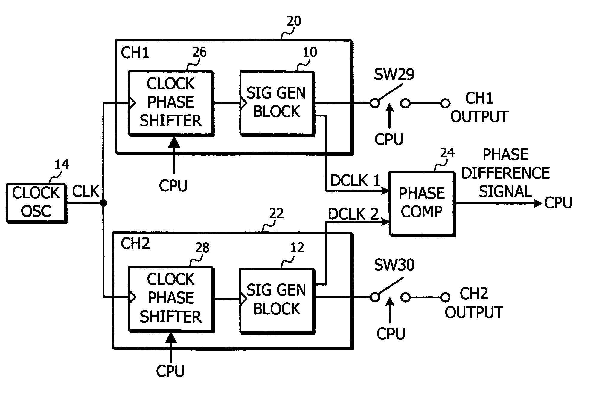
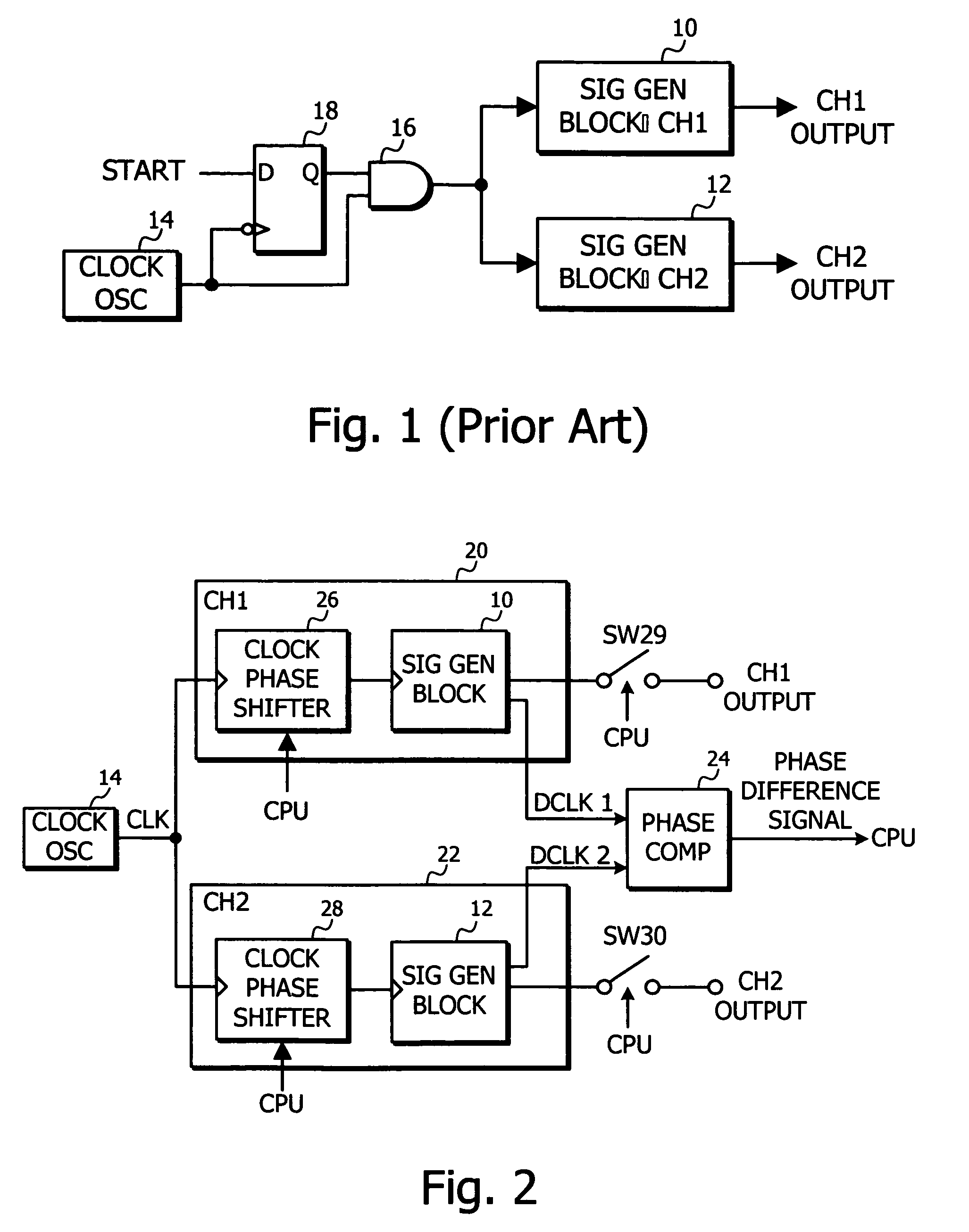
[0026]FIG. 2 is a functional block diagram of an example of a signal generator according to the present invention. The signal generator has a control means that includes a central processing unit (CPU), such as a microprocessor, RAM memory, hard disk drive (HDD), keyboard, and the like, which are not shown. The signal generator operates under program control using programs stored in the RAM memory or on the hard disk drive. The signal generator has outputs channels CH1 OUTPUT and CH2 OUTPUTS providing signal outputs that may be started by a user initiating an output start operation of the signal generator. An external trigger input terminal (not shown) may be provided that operates in conjunction with the control means to control the start of the signal outputs according to an external trigger signal. In the following descriptions, similar elements from previous drawing figure are labeled the same.

[0027]FIG. 2 shows an example the signal generator providing signal outputs from first...


PUM


Abstract

A signal generator can control phase relationship between output signals of the channels without stopping clocks provided to the channels to enable the circuit operation fast. First and second channels 20 and 22 have signal generation blocks 10 and 12 that have clock phase shift circuits 26 and 28, memories, parallel to serial converters and DACs respectively. A phase comparator 24 compares data reading clocks from the signal generation blocks 10 and 12 to produce a phase difference signal wherein the data reading clocks are used to read waveform data from the memories within the signal generation blocks 10 and 12. A CPU controls the clock phase shift circuits 26 and 28 according to the phase difference signal to shift phases of the clocks provided to the signal generation blocks 10 and 12 and then makes phase relationship between the output signals of the first and second channels 20 and 22 as desired.

Description

BACKGROUND OF THE INVENTION[0001]The present invention relates generally to signal generators and more specifically to a signal generator that can accurately control phase relationships between output signal channels and provide faster output signals.[0002]During the design of electronic devices, some of the circuits in the device are produced as prototype circuits but other circuits in the device may not have been completed. In such a case, a signal generator can be used to simulate the output of the preceding circuit stage for confirming the operation of the prototype circuit by providing the simulated signals to the prototype circuit.[0003]Some prototype circuits require multiple stimulation signal to be provided to points of the circuit. Therefore, some the signal generators have multiple signal output channels providing synchronized signal outputs between the channels. The signal outputs of the channels may be started by a user initiating an output start operation of the signal...

Claims


Application Information

Patent Timeline
Patent Type & Authority Patents(United States)
IPC IPC(8): G06F1/04
CPCH03L7/00H03M1/0624H03M1/66
Inventor FUJISAWA, YASUMASAVEITH, RAYMOND L.
Owner TEKTRONIX INC
Why Eureka
Try Eureka