
Data reproduction apparatus

a data and apparatus technology, applied in the field of data reproduction apparatuses, can solve the problems of limited bandwidth of pll, difficulty in increasing the bandwidth of pll, and variable delay elements in the path of sample-value series, and achieve the effect of accurate phase error

Inactive Publication Date: 2006-04-04
PIONEER CORP
View PDF9 Cites 2 Cited by
  • Summary
  • Abstract
  • Description
  • Claims
  • Application Information

AI Technical Summary

Benefits of technology

The present invention provides a data reproduction apparatus that can widen the bandwidth of the PLL and perform stable phase synchronization with good followability, even in the presence of delay factors. The apparatus includes a conversion device, phase correction device, phase detection device, and clock generation device. The phase correction device uses a transversal filter with multiple taps, and the tap coefficients are set based on a phase-error signal. The apparatus can selectively switch the connection of the taps based on the phase-error signal, and can also change the tap positions based on the polarity of the phase-error signal. The apparatus can easily correct the phase of the sample-value series and perform a high-precision filtering.

Problems solved by technology

However, in the data reproduction apparatus described above, there are various delay elements in the path of the sample-value series.
Moreover, when it is not possible to maintain an adequate phase margin, it becomes difficult to increase the bandwidth of the PLL.
For this kind of data reproduction apparatus with PLL, there was a problem in that widening the bandwidth of the PLL was limited by the existence of delay elements.

Method used


Image

  • Data reproduction apparatus
  • Data reproduction apparatus
  • Data reproduction apparatus

Examples


Embodiment Construction

[0040]The preferred embodiment of the invention will be explained based on the drawings. For this embodiment, application of the invention to a data reproduction apparatus, which reproduces user data from a disk-shaped recording medium such as a DVD and outputs that user data to the outside, will be explained.

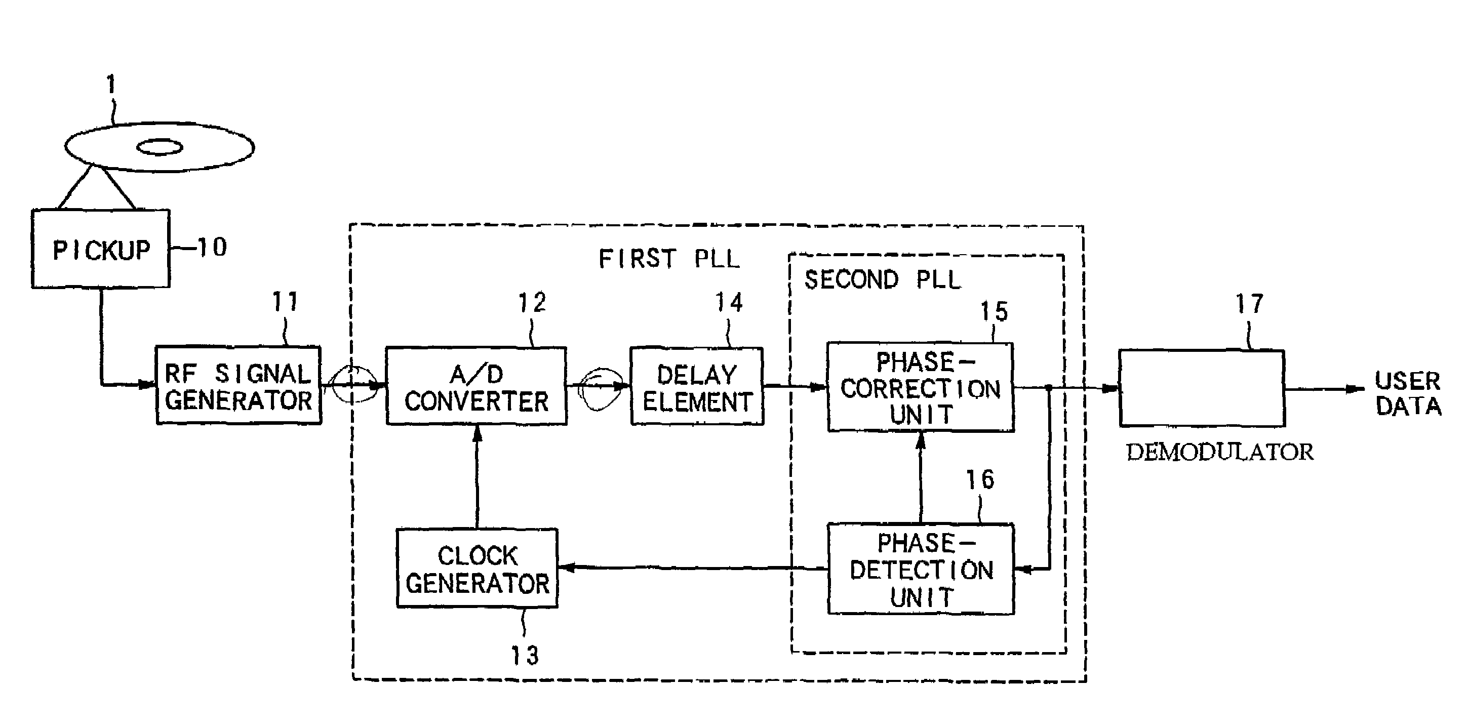
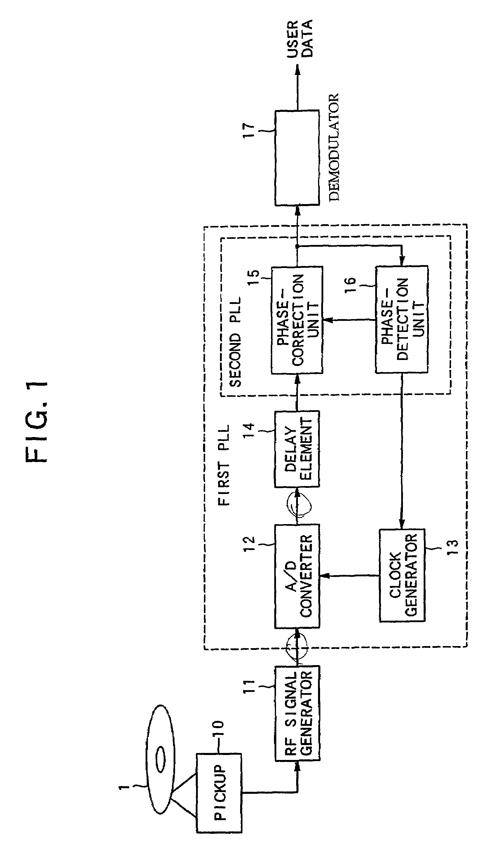
[0041]FIG. 1 is a block diagram showing the major configuration of the data reproduction apparatus of this embodiment of the invention. The embodiment shown in FIG. 1 is provided with a pickup 10 that reproduces the data from a mounted disk 1, a RF signal generator 11, an A / D converter 12, a clock generator 13, a delay element 14, a phase-correction unit 15, a phase-detection unit 16 and a demodulation unit 17. The overall reproduction operation is controlled entirely by a CPU (not shown in the figure), and control signals are sent from the CPU to all of the components.

[0042]A feature of the construction shown in FIG. 1 is a first PLL and a second PLL that follows it. The first...


PUM

PropertyMeasurementUnit
phase-erroraaaaaaaaaa
phaseaaaaaaaaaa
polarityaaaaaaaaaa

Abstract

A data-reproduction apparatus in which an RF signal that is input from a disk to an A / D converter via a pick-up and RF signal generator is sampled according to a sampling clock from a clock generator and converted to a sample-value series. This sample-value series is input to a phase-correction unit via a delay element, and its phase is corrected based on a phase-error signal from a phase-detection unit, then it is demodulated by a demodulator to become user data. On the other hand, the sample-value series, whose phase has been corrected, is input to a phase-detection unit where the phase error is detected, and a generated phase-error signal is then supplied to both the phase-correction unit and the clock generator. In this way a first PLL is followed by a second PLL, which makes it possible to easily widen the bandwidth of the second PLL without including a delay element in the loop.

Description

BACKGROUND OF THE INVENTION[0001]1. Field of the Invention[0002]The present invention relates to the technical field of a data reproduction apparatus for reproducing digital data according to a reproduction signal that is read from a recording medium, and more particularly, to the technical field of a data reproduction apparatus that samples a reproduction signal according to a sampling clock and converts it to a sample-value series, and using a PLL (Phase Locked Loop), performs phase synchronization of the sample-value series.[0003]2. Description of the Related Art[0004]Recently, the use of a data reproduction apparatus, which reproduces digital data using a large-capacity, disk-shaped recording medium such as a DVD, has become popular. In this kind of data reproduction apparatus, an RF signal that corresponds to a pit line on the surface of the disk is read by a pick up, and this analog RF signal is converted to a digital sample-value series by an A / D converter. The sampling clock...

Claims


Application Information

Patent Timeline
Patent Type & Authority Patents(United States)
IPC IPC(8): H03D3/24H04L7/00G11B20/14H03H17/08H03L7/081H03L7/091H03L7/10H04L7/033
CPCG11B20/1426H03L7/091H03L7/081H04L7/0334
Inventor KOBAYASHI, HIDEKIKURIBAYASHI, HIROKI
Owner PIONEER CORP
Learn More