Length sensor

a technology of length sensor and length, applied in the field of length measuring probe, can solve the problem that the long helical spring has a tendency to kink laterally

Inactive Publication Date: 2006-10-17
DR JOHANNES HEIDENHAIN GMBH
View PDF25 Cites 11 Cited by
  • Summary
  • Abstract
  • Description
  • Claims
  • Application Information

AI Technical Summary

Benefits of technology

[0010]It is an object of the present invention to create a length measuring probe which is constructed to be compact and solid,

Problems solved by technology

The length of the helical spring must correspond at least to the lift of the probe pin, however, long helical springs have a tendency to kink laterally.
In the case where a large

Method used


Image

  • Length sensor
  • Length sensor
  • Length sensor

Examples


Embodiment Construction

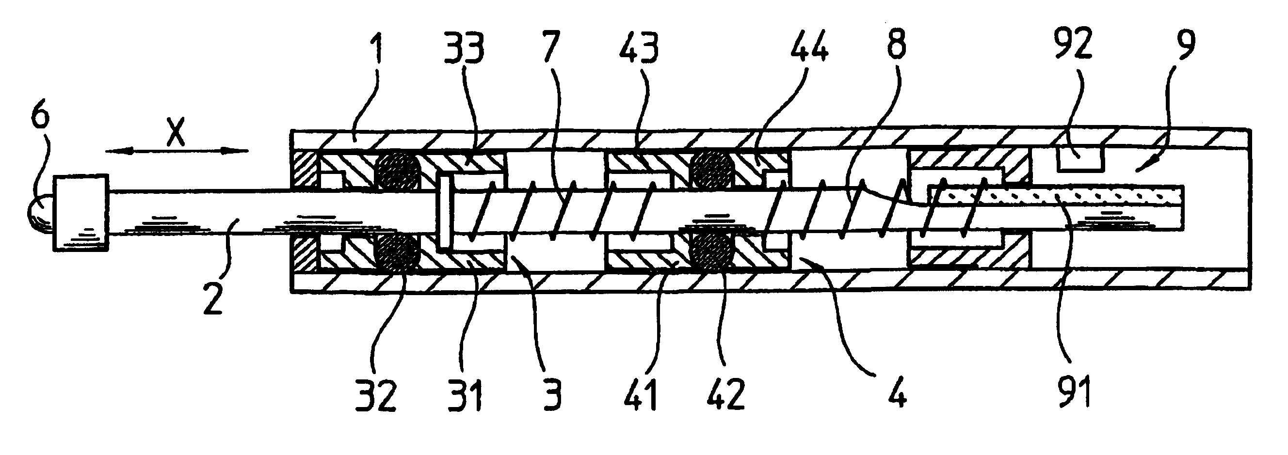
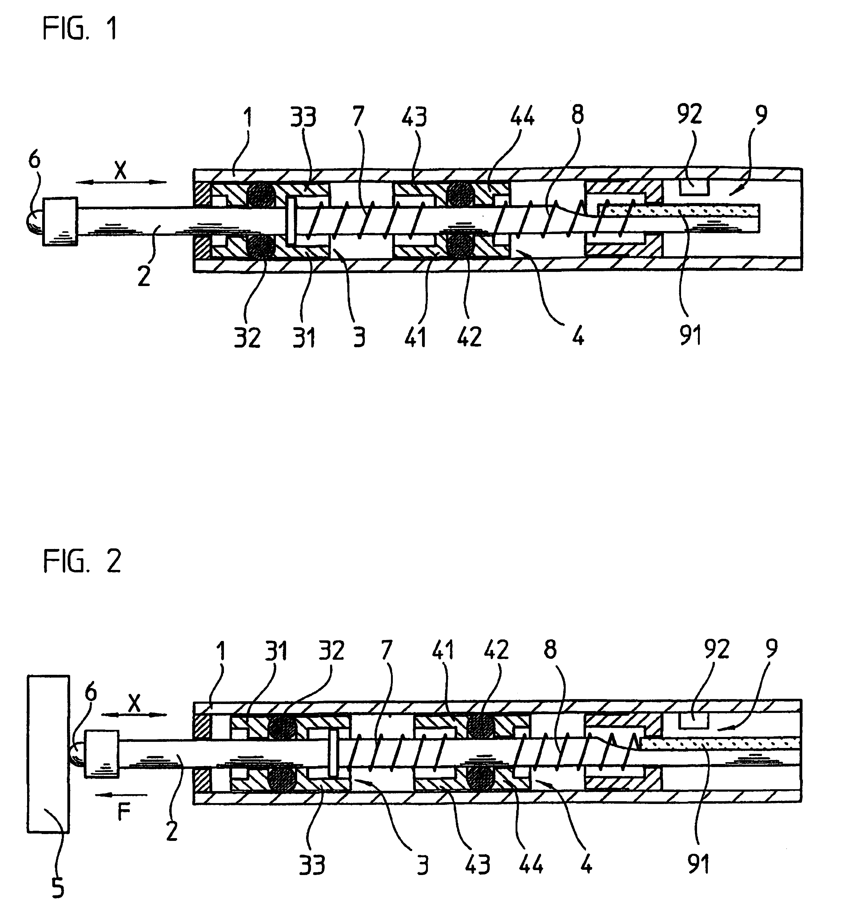
[0020]An exemplary embodiment of a length measuring probe designed in accordance with the present invention will be described in what follows by FIGS. 1 and 2. The drawing figures schematically show a cross section of the entire length measuring probe, includes a base body 1 in which a rod-shaped probe pin 2 is seated, displaceable in the measuring direction X.

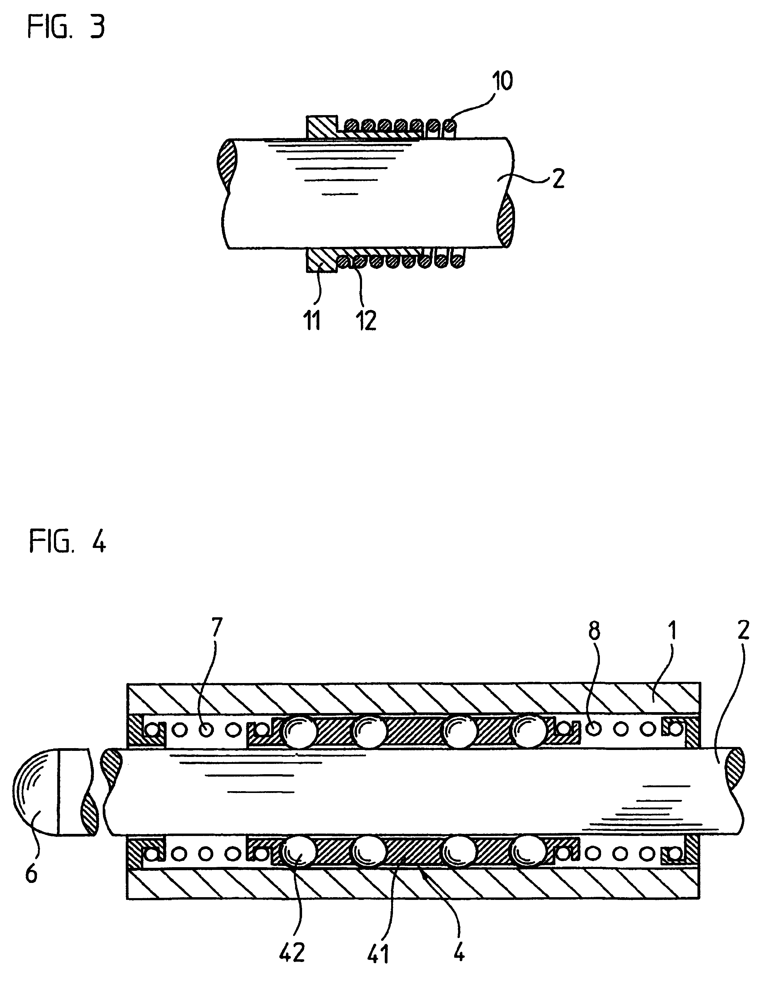
[0021]For touch scanning a workpiece 5 represented in FIG. 2, the end of the probe pin 2 is spherically designed as a touch scanning element 6. In the course of a touch scanning process, the touch scanning element 6 of the probe pin 2 is forced with a force F onto the surface of the workpiece 5 to be measured. This force F is generated by helical springs 7 and 8, which are arranged one behind the other in the measuring direction X and force the touch scanning element 6 onto the workpiece 5. For a space-saving construction, the windings of the helical springs 7, 8 extend around the circumference of the round probe pin 2. For pr...


PUM


Abstract

A length measuring probe that includes a base body, a guide element and a probe pin having a touch scanning element for touch scanning a measuring object, the probe pin is seated, displaceable in relation to the base body in a measuring direction opposite a spring force F via the guide element. A detection device detects a position of the probe pin with respect to the base body and a first spring element and a second spring element arranged behind the first spring element in the measuring direction so as to prestress the probe pin. The guide element is arranged between the first and second spring elements, on which facing end areas of the first and second spring elements are fixed in place, and wherein the at least one guide element is seated, displaceable in the measuring direction, on the probe pin and on the base body.

Description

[0001]Applicants claim, under 35 U.S.C. §§ 120 and 365, the benefit of priority of the filing date of Mar. 28, 2002 of a Patent Cooperation Treaty patent application, copy attached, Ser. No. PCT / EP02 / 03478, filed on the aforementioned date, the entire contents of which are incorporated herein by reference, wherein Patent Cooperation Treaty patent application Ser. No. PCT / EP02 / 03478 was not published under PCT Article 21(2) in English.[0002]Applicants claim, under 35 U.S.C. § 119, the benefit of priority of the filing date of Apr. 11, 2001 of a German patent application, copy attached, Serial Number 101 18 069.1, filed on the aforementioned date, the entire contents of which are incorporated herein by reference.BACKGROUND OF THE INVENTION[0003]1. Field of the Invention[0004]The present invention relates to a length measuring probe.[0005]2. Description of the Related Art[0006]Such length measuring probes are employed in manufacturing technology for measuring workpieces. For example, t...

Claims


Application Information

Patent Timeline
IPC IPC(8): G01B3/00G01B3/22G01B5/02G01B11/00G01B21/00
CPCG01B3/002G01B3/008G01B3/22G01B11/00
Inventor HERKT, PETERBOGE, LUDWIG
Owner DR JOHANNES HEIDENHAIN GMBH
Why Eureka
Try Eureka