Air intake valve lift-variable system in air intake pressure regulating type

A technology of intake pressure and intake valve, applied in engine components, machines/engines, mechanical equipment, etc., can solve problems such as high sealing requirements, liquid leakage, delay in response speed of valve lift changes, etc. Fast speed, simple structure, reasonable design effect

Inactive Publication Date: 2012-12-05
SHANGHAI JIAO TONG UNIV
View PDF8 Cites 6 Cited by
  • Summary
  • Abstract
  • Description
  • Claims
  • Application Information

AI Technical Summary

Problems solved by technology

However, its design is to use a hydraulic mechanism, which requires high sealing performance. If the sealing is not tight, it will easily c

Method used


Image

  • Air intake valve lift-variable system in air intake pressure regulating type
  • Air intake valve lift-variable system in air intake pressure regulating type

Examples


Embodiment

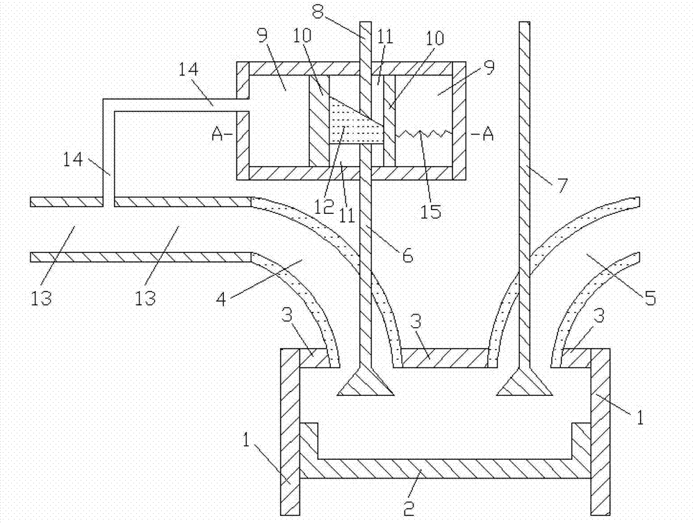
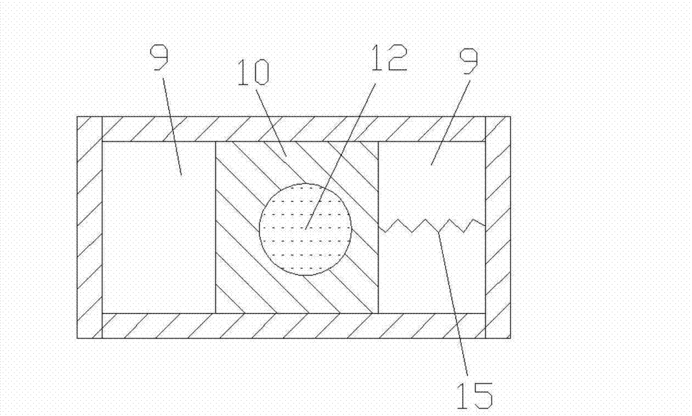
[0014] like figure 1 and figure 2 As shown, the present invention includes: comprising cylinder 1, piston 2, cylinder head 3, intake passage 4, exhaust passage 5, intake valve lower section 6, exhaust valve 7, intake valve upper section 8, volume chamber 9, moving Body 10, through pipe 11, moving block 12, intake pipe 13, connecting pipe 14 and spring 15, the piston 2 is installed in the space surrounded by the cylinder 1 and is in sealing contact with the inner wall surface of the cylinder 1, the outlet of the intake passage 4 The gas port and the air inlet of the exhaust passage 5 are all connected with the cylinder head, the lower end surface of the lower section 6 of the intake valve and the lower end surface of the exhaust valve 7 are all in the combustion chamber, and the moving body 10 is installed in the volume chamber 9 and connected with the volume chamber. The inner wall surface of the chamber 9 is in sealing contact, the penetrating pipe 11 runs through the upper...


PUM


Abstract

The invention discloses an air intake valve lift-variable system in an air intake pressure regulating type, belonging to the technical field of internal combustion engines. The system comprises an air intake channel, an air exhaust channel, an air intake valve lower section, an air exhaust valve, an air intake valve upper section, a capacity cavity, a movable body, a perforation pipe, a movable block, an air inlet pipe, a connecting pipe and a spring, wherein the movable body is mounted in the capacity cavity and is contacted with the inner wall face of the capacity cavity in a sealing manner; the perforation pipe perforates the upper wall face and the lower wall face of the movable body; the movable block is mounted in the perforation pipe and is contacted with the inner wall face of the perforation pipe in a sealing manner; the lower end face of the movable block is a plane; the upper end face of the movable block is an inclined face; two ends of the connecting pipe are communicated with the left wall faces of the air intake pipe and the capacity cavity; the right wall face of the movable body is connected with the right wall face of the capacity cavity through the spring; when pressure in the air intake pipe is relatively large, the movable body is moved to right; the air intake valve lift is increased; when the pressure in the air intake pipe is relatively small, the movable body is moved to left; the air intake valve lift is reduced; and the intake valve variable-lift system is characterized by reasonable design and simple structure and is suitable for engine valve lift-variable systems.

Description

technical field [0001] The invention relates to an engine intake system in the technical field of internal combustion engines, in particular to an intake pressure adjustable intake valve lift variable system. Background technique [0002] The valve lift of the traditional gasoline engine is fixed and invariable, that is, there is only one cam profile of the camshaft, which makes it impossible for the lift to make the engine respond well in both high-speed and low-speed areas. The valve lift or cam profile design of a traditional gasoline engine is a balanced choice for the engine under all operating conditions. As a result, the engine can neither get the best high-speed efficiency nor the best low-speed torque, but it can get The most balanced performance under all working conditions. The adoption of variable valve lift enables the engine to obtain the required valve lift in both high-speed and low-speed areas, thereby improving the high-speed power and low-speed torque of ...

Claims


Application Information

Patent Timeline
IPC IPC(8): F01L1/34F01L13/00
Inventor 石磊邓康耀吴重敏
Owner SHANGHAI JIAO TONG UNIV
Why Eureka
Try Eureka