Aircraft generating larger lift by reduction of fluid resistance

a technology of fluid resistance and aircraft, applied in the field of aircraft, can solve the problems of only about 10% of the energy utilization rate of the moving device, and the moving device consumes about 90% of the power

Active Publication Date: 2020-01-16
ZHU XIAOYI
View PDF0 Cites 6 Cited by
  • Summary
  • Abstract
  • Description
  • Claims
  • Application Information

AI Technical Summary

Benefits of technology

[0006]In the invention, the flow speed on upper surfaces of wings is increased to generate a larger pressure difference between the upper surfaces and lower surfaces of the wings, and the upper surfaces and the lower surfaces of the wings are communicated via a plurality of air vents to directly transfer a high pressure generated on the lower surfaces of the wings towards a low pressure generated on the upper surfaces of the wings in a direction opposite to an external fluid pressure on the upper surfaces of the wings so as to counteract the external fluid pressure. With the increase of the flow speed difference between the upper surfaces and lower surfaces of the wings, more fluid resistance will be reduced, and a larger lift will be generated.
[0011]The invention has the following beneficial effects: according to common knowledge, a lift is indirectly generated after fluid flows through the upper surfaces and the lower surfaces of the wings along different paths to reach the rear parts at the same time to be converged, and fluid resistance is generated at the same time.

Problems solved by technology

As is known to all, moving devices consume about 90% of power to overcome the fluid resistance, which means that the energy utilization rate of the moving devices is only about 10%.

Method used


Image

  • Aircraft generating larger lift by reduction of fluid resistance
  • Aircraft generating larger lift by reduction of fluid resistance

Examples


embodiment 1

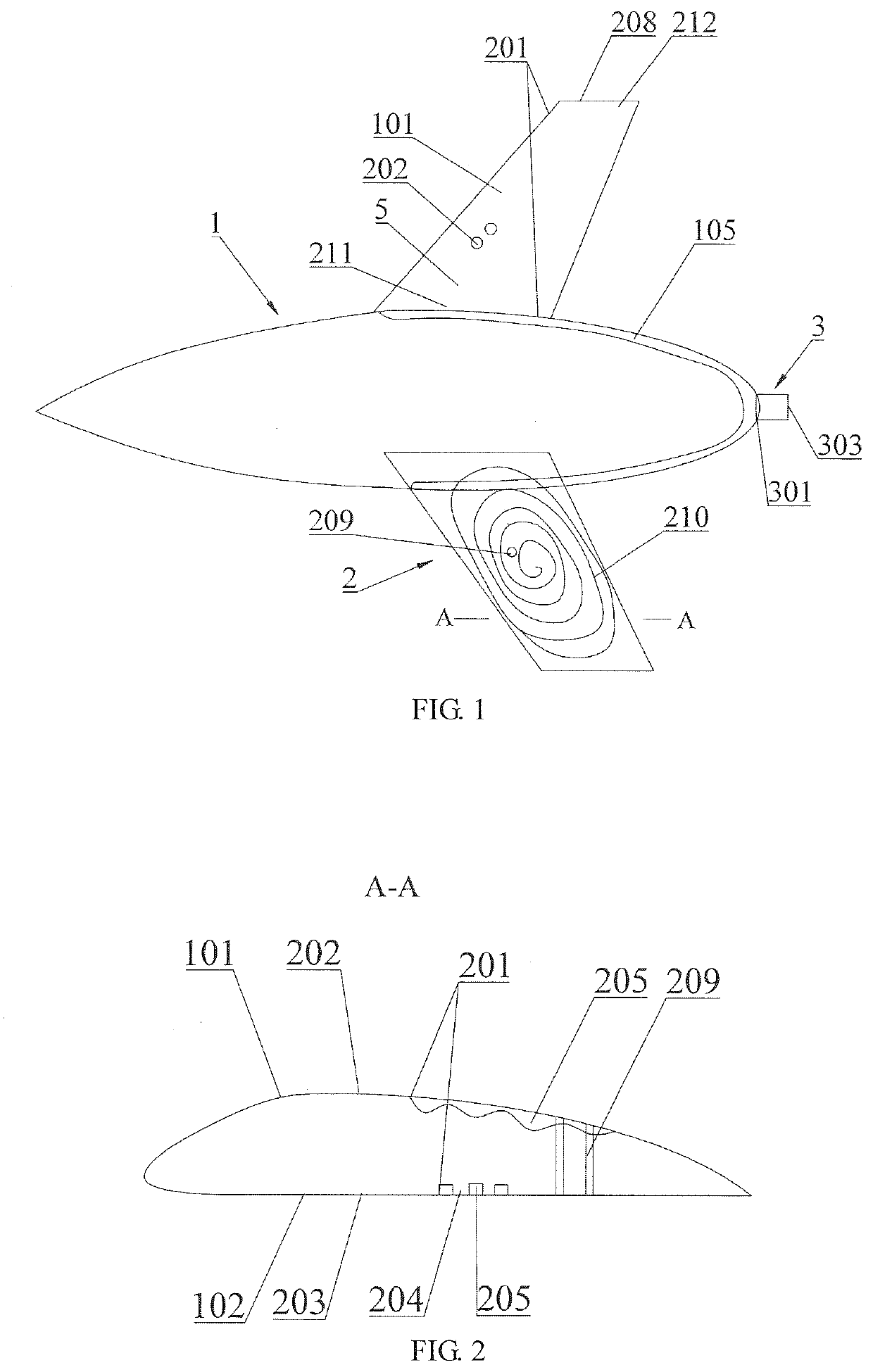
[0027]Referring to FIG. 1-FIG. 3, an aircraft comprises a fuselage 1 and wings 2, wherein a plurality of first pressure ports 203 (small holes) are formed in lower surfaces 102 of the wings and are communicated with first channels 201 in the wings 2, first inlets 202 are uniformly formed in upper surfaces 101 of the wings from roots 211 of the wings to tails 212 of the wings and are communicated with the first channels 201, first outlets 208 are formed in the tails of the wings 2 and are communicated with the first channels 201, and fluid flows through the wings in a lengthwise direction and is discharged via the first outlets 208 at the tails; spoiler devices are arranged in the first channels 201 of the wings to extend the paths of the fluid flowing through the first channels in the lengthwise direction of the wings and are located on a side towards the upper surfaces 101 or a side towards the lower surfaces 102, and the spoiler devices are arranged in part of the first channels ...

embodiment 2

[0040] this embodiment differs from Embodiment 1 in that a plurality of rows of first inlets 202 are uniformly formed in the upper surfaces 101 of the wings from roots 211 to tails 212 in the lengthwise direction and are communicated with the first channel 201, so that two high-speed fluid layers 5 which are communicated with each other and have approximately identical flow speeds are formed by the upper surfaces of the wings and the first channel 201 to guide the fluid to flow through the upper surfaces of the wings in the lengthwise direction. A plurality of rows of pressure pipes 209 (small holes) are uniformly on the lower surfaces 102 of the wings in the widthwise direction and are communicated with the upper surfaces of the wings (fluid naturally flows through the upper surfaces and lower surfaces of the wings in the widthwise direction); under the fluid continuity, the fluid flows through the upper surfaces 101 of the wings in the lengthwise direction and flows through the lo...

embodiment 3

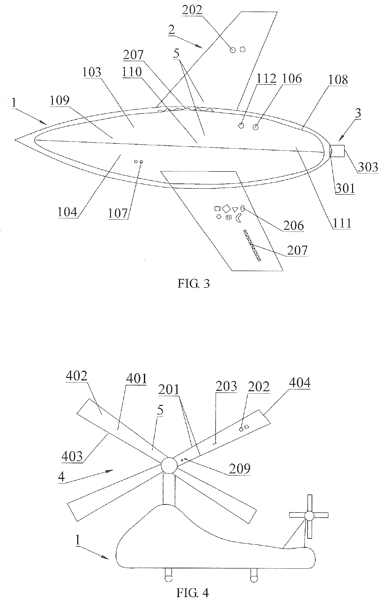
[0042] as shown in FIG. 3, this embodiment differs from Embodiment 1 in the following aspects: the fuselage 1 comprises an upper half 103 and a lower half 104, a third channel 108 is formed in a shell around the fuselage 1, a plurality of second inlets 106 are uniformly formed in the upper half of the fuselage and are communicated with the third channel 108, and a plurality of second pressure ports 107 are uniformly formed in the lower half of the fuselage and are communicated with the third channel 108. The opening area of the second inlets 107 is larger than that of the second pressure ports 107, and spoiler devices are arranged in the third channel 108 corresponding to the upper half 103 of the fuselage to extend the fluid path and to increase the flow speed, so that high-speed fluid layers 5 are formed in the shell of the upper half 103 of the fuselage and the corresponding third channel 108, a pressure difference is generated due to different flow speeds of the high-speed fluid...


PUM


Abstract

The invention discloses a lift source for an aircraft comprising a fuselage and wings, wherein first channels are formed in the wings, a plurality of first inlets are formed in upper surfaces of the wings, a plurality of first pressure ports are formed in lower surfaces of the wings and are communicated with the first inlets via the first channels; and spoiler devices are arranged in the first channels and under the effect of the spoiler devices, form high-speed fluid layers on the upper surfaces of the wings, thereby generating a pressure difference from the lower surfaces of the wings which counteracts an external fluid pressure on the upper surfaces of the wings in the opposite direction, so a lift is generated by reduction of fluid resistance when fluid flows through the upper and lower surfaces of the wings, thereby developing a high-speed aircraft with a larger lift and thrust.

Description

CROSS-REFERENCE TO RELATED APPLICATIONS[0001]This application is a continuation of International Application No. PCT / CN2018 / 091827, filed Jun. 19, 2018, which claims the benefit of Chinese Application No. 201710282079.5, filed Apr. 26, 2017, in the China National Intellectual Property Administration. All disclosures of the documents named above are incorporated herein by reference.TECHNICAL FIELD[0002]The invention relates to the technical field of aircrafts, in particular to an aircraft generating a larger lift by reduction of fluid resistance.DESCRIPTION OF RELATED ART[0003]Due to the small difference between upper arc surfaces and lower planar surfaces of the wings of fixed-wing aircrafts, the lift generated by the fixed-wing aircrafts is small. The lift and thrust generated by rotary-wing aircrafts driven by propellers are also small. Meanwhile, all aircrafts will inevitably generate great fluid resistance in the course of generating a lift, and most energy of the aircrafts is c...

Claims


Application Information

Patent Timeline
Patent Type & Authority Applications(United States)
IPC IPC(8): B64C21/02B64C27/06B64C1/00B64C1/26B64D27/02B64C3/58B64C3/14B64C27/467
CPCB64D27/02B64C2003/148B64C1/0009B64C27/467B64C3/14B64C2230/08B64C27/06B64C1/26B64C3/58B64C2230/28B64C21/02B64C3/00B64C21/04B64C21/06B64C2003/143B64C2230/04B64C2230/20Y02T50/10Y02T50/60
Inventor ZHU, XIAOYI
Owner ZHU XIAOYI
Why Eureka
Try Eureka