
Support structure for a back part and/or a seat of a seat assembly and seat assembly comprising such a support structure

a support structure and back part technology, which is applied in the direction of vehicle seats, seating furniture, transportation and packaging, etc., can solve the problems of reducing the minimum reset torque, and reducing the reset torqu

Inactive Publication Date: 2011-07-28
STOLL GIROFLEX
View PDF17 Cites 37 Cited by
  • Summary
  • Abstract
  • Description
  • Claims
  • Application Information

AI Technical Summary

Benefits of technology

[0011]It is an object to avoid the abovementioned disadvantages and to create a support structure or a seat assembly, respectively, comprising a power system, which makes it possible to be able to change the reset force, which is in each case generated by the power system, across the largest possible range in a simple and comfortable manner, so that the power system can be adapted to the requirements of different persons with large differences with regard to their weight in a simple and comfortable manner.

Problems solved by technology

The mentioned elastomer torsion spring element has the disadvantage that the reset torque, which is generated in response to a rotation of the mentioned shaft about a certain angle of rotation, shows a relatively low increase as function of the respective angle of rotation, in particular when the elastomer torsion spring element is not or only slightly prestressed.
It is thus time-consuming and laborious to vary the minimum reset torque by manually twisting the outer housing relative to the inner housing across a large area.
The resilience of the power system is thus limited.
This is so because, as a rule, the coupling device or the respective spring element is not easily accessible to a user.

Method used


Image

  • Support structure for a back part and/or a seat of a seat assembly and seat assembly comprising such a support structure
  • Support structure for a back part and/or a seat of a seat assembly and seat assembly comprising such a support structure
  • Support structure for a back part and/or a seat of a seat assembly and seat assembly comprising such a support structure

Examples


Embodiment Construction

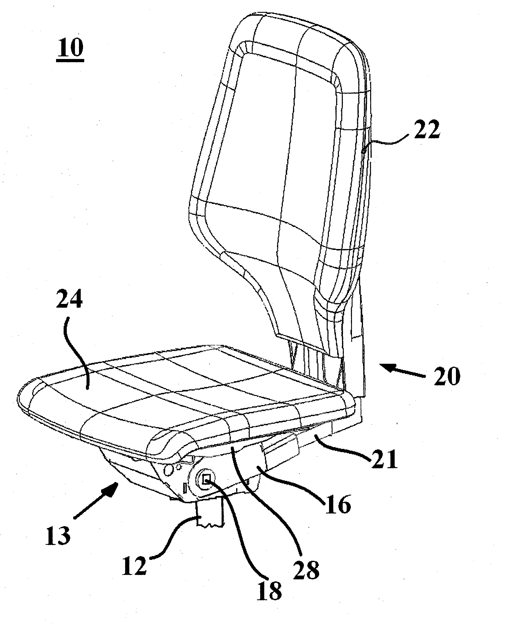
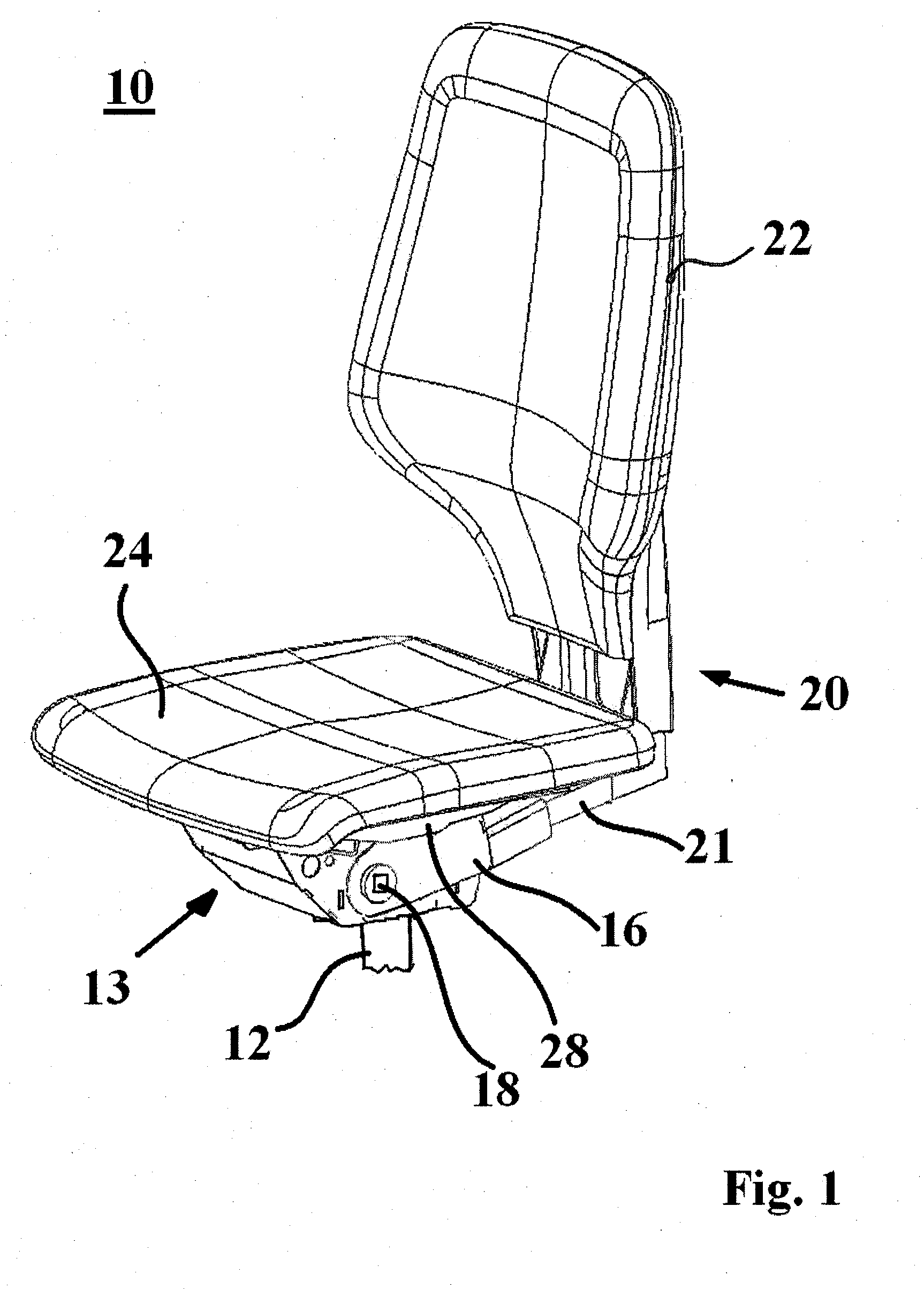
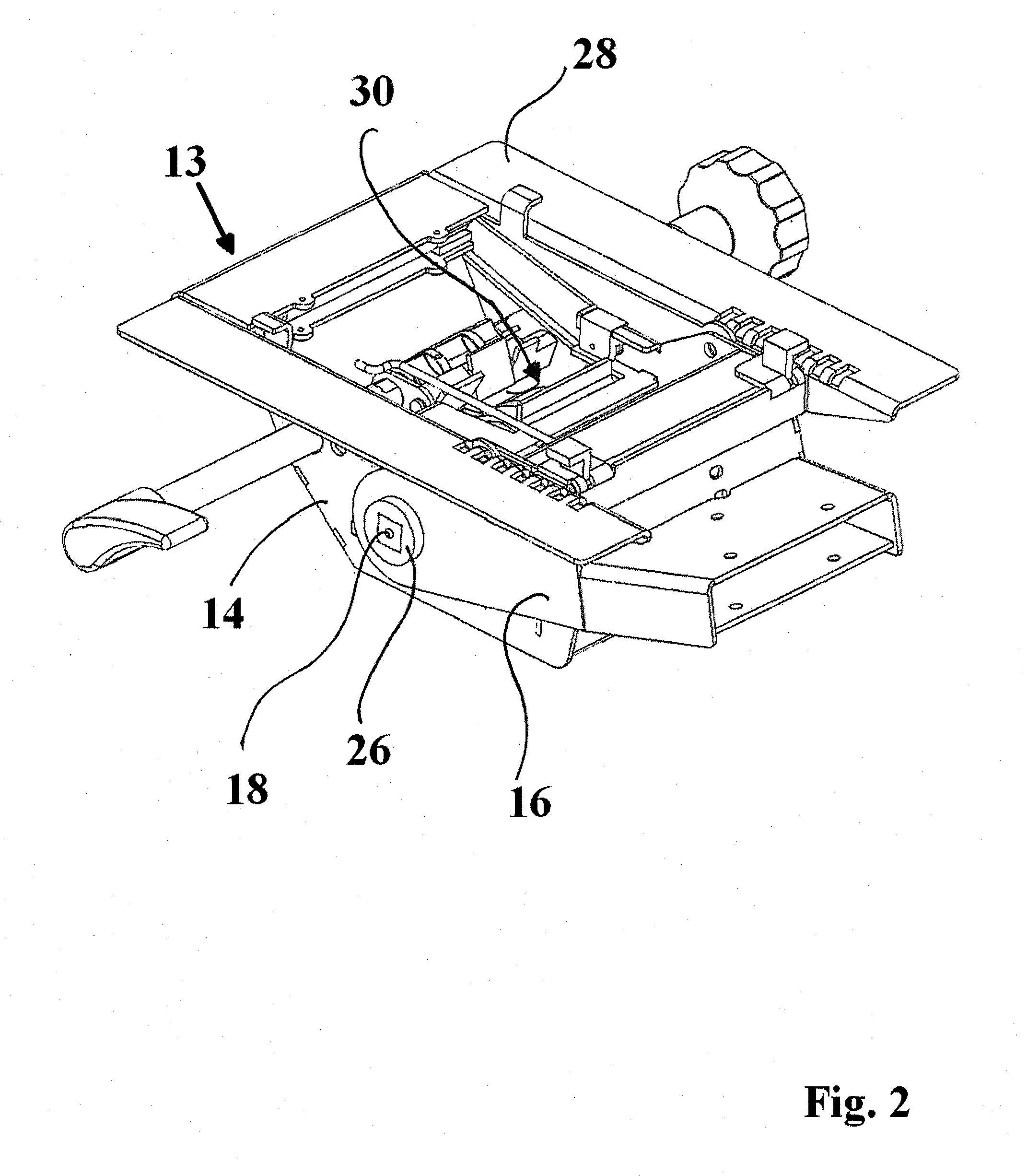
[0063]FIG. 1 shows an exemplary embodiment of a seat assembly in the form of a chair 10. The chair 10 is embodied as an office swivel chair. It comprises a support column 12, a back part 20, a seat 24 and a support structure 13 according to an embodiment of the invention for the back part 20 and for the seat 24. The support structure 13 holds the back part 20 and the seat 24 in a basic position in each case, provided that no load acts on the back part 20 or on the seat 24, respectively, and makes it possible for the back part 20 or the seat 24, respectively, to be able to be deflected out of the respective basic position, provided that a load acts on the back part or on the seat 24, respectively. In the illustration according to FIG. 1, the back part 20 or the seat 24, respectively, are unloaded and are thus in the respective basic position. In this basic position, the back part 22 is oriented in a substantially vertical manner and the seat 24 is oriented in a substantially horizont...


PUM


Abstract

A support structure for a back part and / or a seat of a seat assembly includes a base support, a support part, and a power system. The support part is arranged on the base support to support and / or hold the respective back part and / or seat, and is attached to the base support to allow movement of the support part relative to the base support. The power system, which includes first and second spring elements and a coupling device, generates a reset force in response to (and directed opposite to) the respective movement of the support part. When the coupling device is in a first state, the second spring element generates a second reset force directed opposite to the movement of the support part. When the coupling device is in the second state, the second spring element does not generate the second reset force.

Description

CROSS-REFERENCE TO RELATED APPLICATION[0001]This application claims the priority benefit of European Patent Application No. EP 10405014, filed on Jan. 22, 2010, the entirety of which is hereby incorporated by reference.BACKGROUND[0002]1. Field of Invention[0003]The invention relates to a support structure for a back part and / or a seat of a seat assembly and to a seat assembly comprising such a support structure.[0004]2. Related Art[0005]For the most part, seat assemblies, for example chairs, have a modular structure: in addition to a seat and a back part, if necessary, which can comprise a backrest, for example, they normally also comprise a support structure for the respective back part and / or the respective seat, wherein it is the object of the support structure to hold the seat and the back part, if necessary, in a certain position and to accommodate a load, which can be transferred onto the seat or the back part, respectively, by a person sitting on the seat assembly, for exampl...

Claims


Application Information

Patent Timeline
Patent Type & Authority Applications(United States)
IPC IPC(8): A47C1/024
CPCA47C1/03255A47C1/03288A47C1/03266A47C1/03277
Inventor PFEIFER, STEPHANEMMENEGGER, WOLFGANG
Owner STOLL GIROFLEX
Learn More