Thermal mass flow rate sensor having fixed bypass ratio

a mass flow rate sensor and bypass ratio technology, applied in the field of mass flow rate sensors, can solve the problems of multi-gas bypass ratio error, bp error, and reynolds loss being a major source of error in measuring gas flow, etc., to achieve compact size, simple design, and low manufacturing cost

Active Publication Date: 2006-10-17
MKS INSTR INC
View PDF12 Cites 28 Cited by
  • Summary
  • Abstract
  • Description
  • Claims
  • Application Information

AI Technical Summary

Benefits of technology

[0016]Among other features and benefits, the mass flow rate sensor of the present disclosure operates substantially independently of gas properties since the flow restrictors provide the flow sensing apparatus with a fixed flow ratio. In addition, the mass flow rate sensor of the present disclosure is relatively simple in design, inexpensive to manufacture, and compact in size.

Problems solved by technology

εbp translates directly into a calibration error for the new gas.
The multi-gas bypass ratio error εbp occurs because the bypass ratio η changes for different gases because of pressure losses, such as entrance effects, caused by non-ideal geometric conditions of the primary conduit, the bypass tube and the sensor tube.
The Reynolds Losses can be a major source of error in measuring the gas flow.
Properly designing the bypass tube 18a, however, often results in a complex, relatively large and expensive sensor 10, especially at high flow ranges.

Method used


Image

  • Thermal mass flow rate sensor having fixed bypass ratio
  • Thermal mass flow rate sensor having fixed bypass ratio
  • Thermal mass flow rate sensor having fixed bypass ratio

Examples


Embodiment Construction

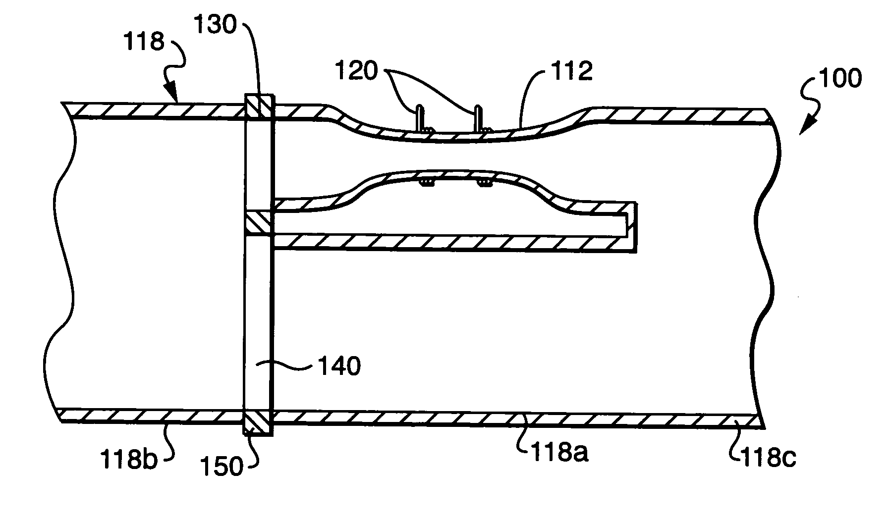
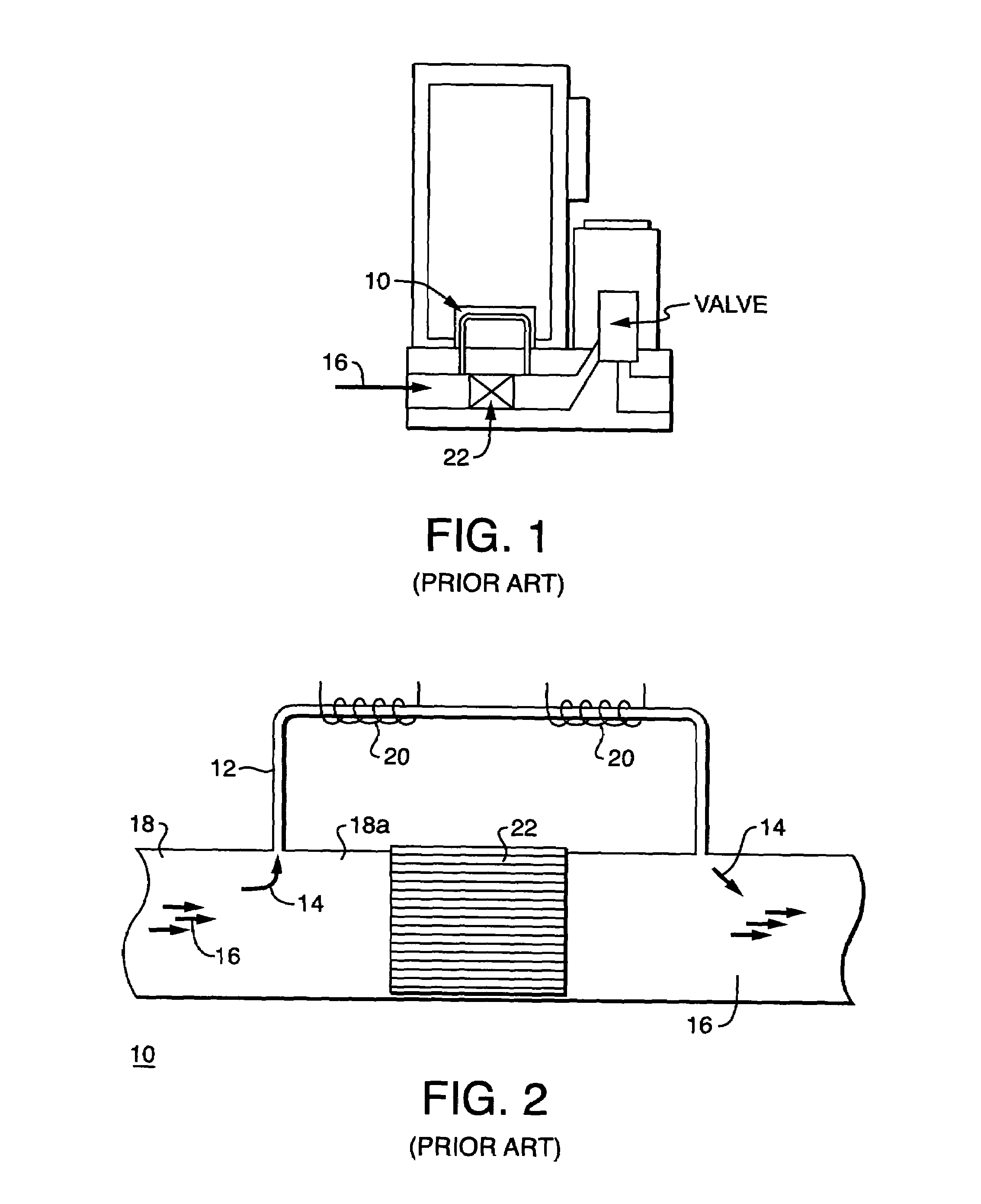
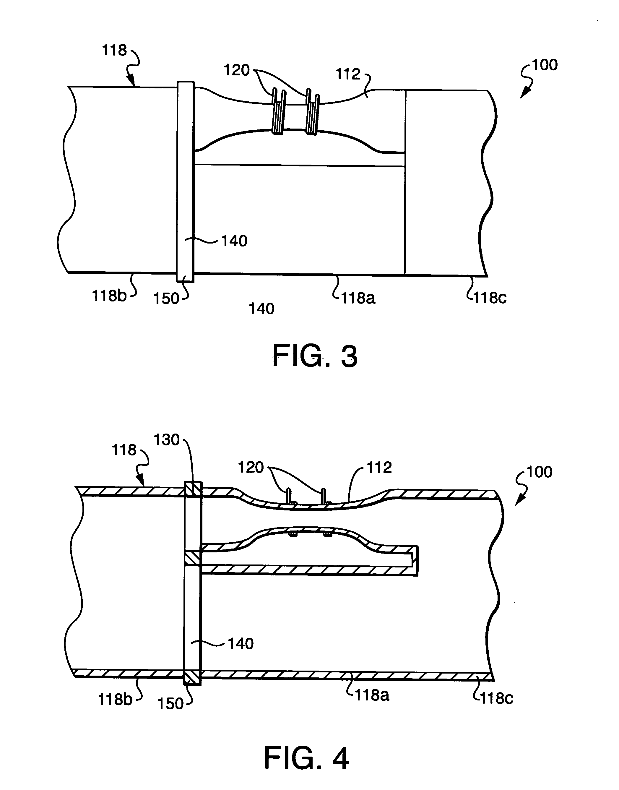
[0025]Referring to the drawings, FIGS. 3 and 4 show an exemplary embodiment of a flow rate sensor 100 constructed in accordance with the present disclosure. The flow rate sensor 100 can be used as part of a mass flow rate controller, such as the mass flow rate controller shown in FIG. 1. In such an application, the flow rate sensor 100 of the present disclosure replaces the flow rate sensor 10 shown in FIGS. 1 and 2. The present disclosure is also directed to a method of measuring flow and a method of controlling flow using the flow rate sensor 100 of FIGS. 3 and 4.

[0026]Among other features and benefits, the mass flow rate sensor 100 of the present disclosure operates substantially independently of gas properties. In addition, the mass flow rate sensor 100 of the present disclosure is relatively simple in design, inexpensive to manufacture, and compact in size.

[0027]In general, the flow rate sensor 100 includes a main conduit 118 including an upstream portion 118b and a downstream ...


PUM


Abstract

A flow rate sensor includes a main conduit, a sensor tube and a bypass tube connecting an upstream portion of the main conduit to a downstream portion of the main conduit such that flow through the main conduit is divided through the sensor tube and the bypass tube, and at least one heater element for heating the sensor tube. A first flow restrictor of porous media is positioned between the upstream portion of the main conduit and the sensor tube, and a second flow restrictor of porous media is positioned between the upstream portion of the main conduit and the bypass tube. The flow restrictors provide the flow rate sensor with a fixed bypass ratio so that the sensor can operate independently of the type of gas being measured.

Description

FIELD OF THE INVENTION[0001]The present disclosure relates to mass flow rate sensors, and more particularly, to a thermal based mass flow rate sensor having a sensor tube and at least one bypass tube, wherein the bypass tube and the sensor tube contain porous media that provide the sensor with a fixed bypass ratio.BACKGROUND OF THE DISCLOSURE[0002]In the semiconductor manufacturing industry, it is necessary to achieve precise control of the quantity, temperature and pressure of one or more reactant materials which are delivered in a gaseous state to a reaction chamber. Mass flow controllers are widely used in the semiconductor manufacturing industry to control the delivery of process reactants. In FIG. 1 there is shown an example of a typical mass flow rate controller (MFC). The MFC generally includes a mass flow rate sensor (which includes a sensor tube and bypass tube, as described below) for measuring the rate of flow of gas through the MFC, a valve for controlling the flow of ga...

Claims


Application Information

Patent Timeline
Patent Type & Authority Patents(United States)
IPC IPC(8): G01F1/68
CPCG01F1/6847G01F5/00G01F5/005G01F1/684G01F1/68
Inventor SHAJII, ALIMENEGHINI, PAULSMITH, DANIEL ALEXANDER
Owner MKS INSTR INC
Why Eureka
Try Eureka