Device for and method of coupling shafts, image formation apparatus, process cartridge, and belt unit

a technology of coupling shaft and image formation apparatus, which is applied in the direction of couplings, slip couplings, instruments, etc., can solve the problems of unfavorable photosensitive member rotation, low coupling accuracy, and poor image quality

Inactive Publication Date: 2006-10-17
RICOH KK
View PDF18 Cites 91 Cited by
  • Summary
  • Abstract
  • Description
  • Claims
  • Application Information

AI Technical Summary

Benefits of technology

[0009]It is an object of the present invention to solve at least the problems in the conventional technology.

Problems solved by technology

However, even if the motor of high-precision is used, if the central axes of the rotating shaft of the motor and the shaft supporting the photosensitive member are displaced from each other at a position in which the shafts are coupled, the rotation of the photosensitive member becomes non-uniform.
As a result, deterioration in image quality caused by unevenness of the image called banding or a positional deviation in a sub-scanning direction of the photosensitive member on the surface of the photosensitive member is caused.
In other words, the coupling between the shafts is not highly precise because the rotating shaft of the photosensitive member and the shaft of the motor are not completely integrated with each other.
Consequently, there is a possibility that the central axes of the coupled shafts may be displaced from each other.

Method used


Image

  • Device for and method of coupling shafts, image formation apparatus, process cartridge, and belt unit
  • Device for and method of coupling shafts, image formation apparatus, process cartridge, and belt unit
  • Device for and method of coupling shafts, image formation apparatus, process cartridge, and belt unit

Examples


Embodiment Construction

[0035]Exemplary embodiments of the present invention are described below with reference to the accompanying drawings.

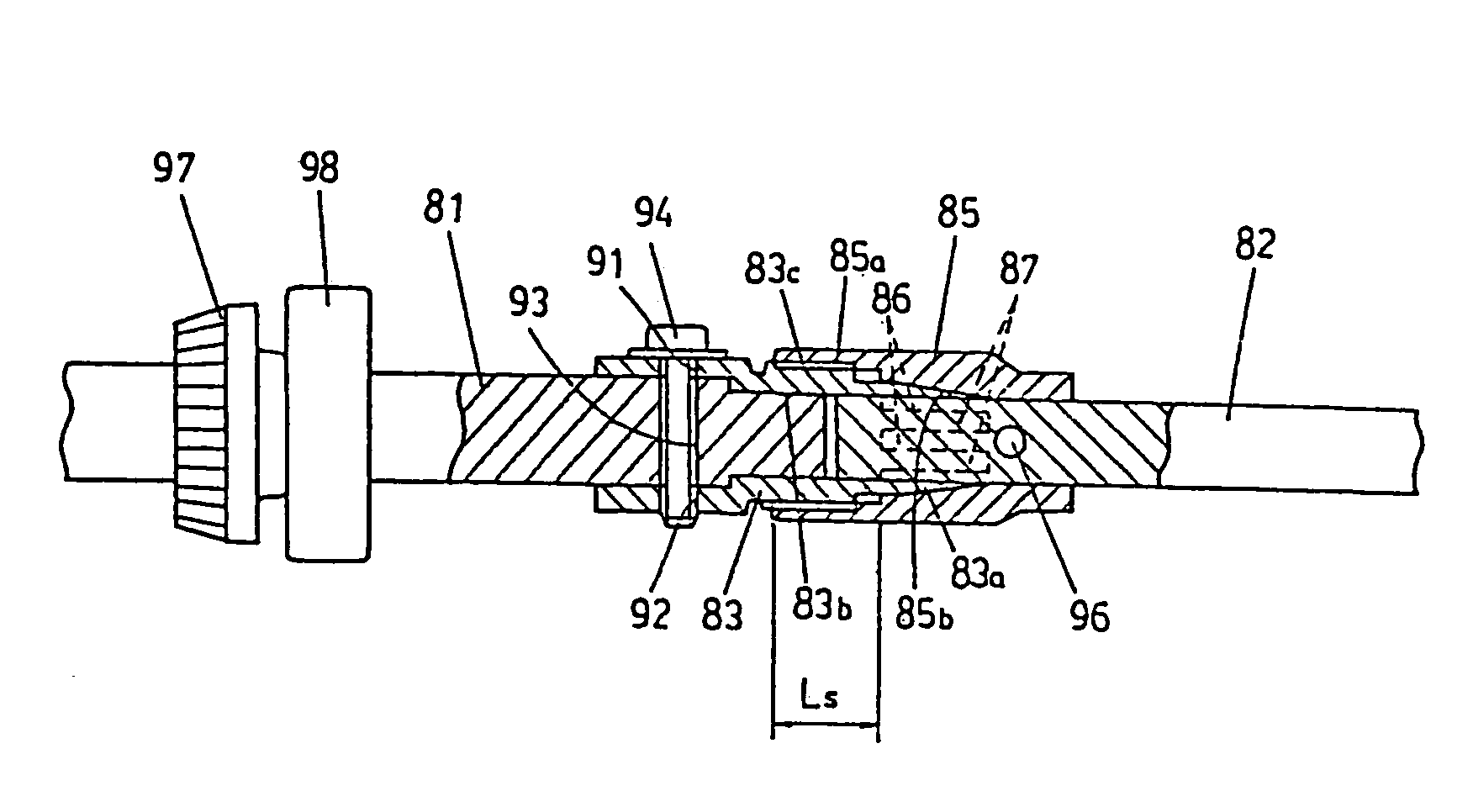
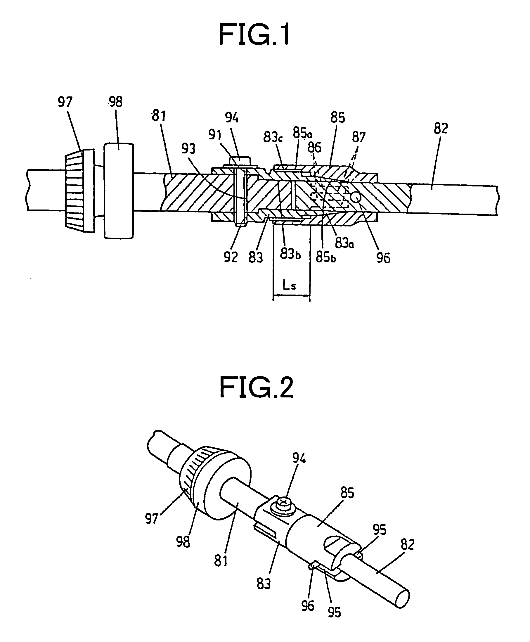
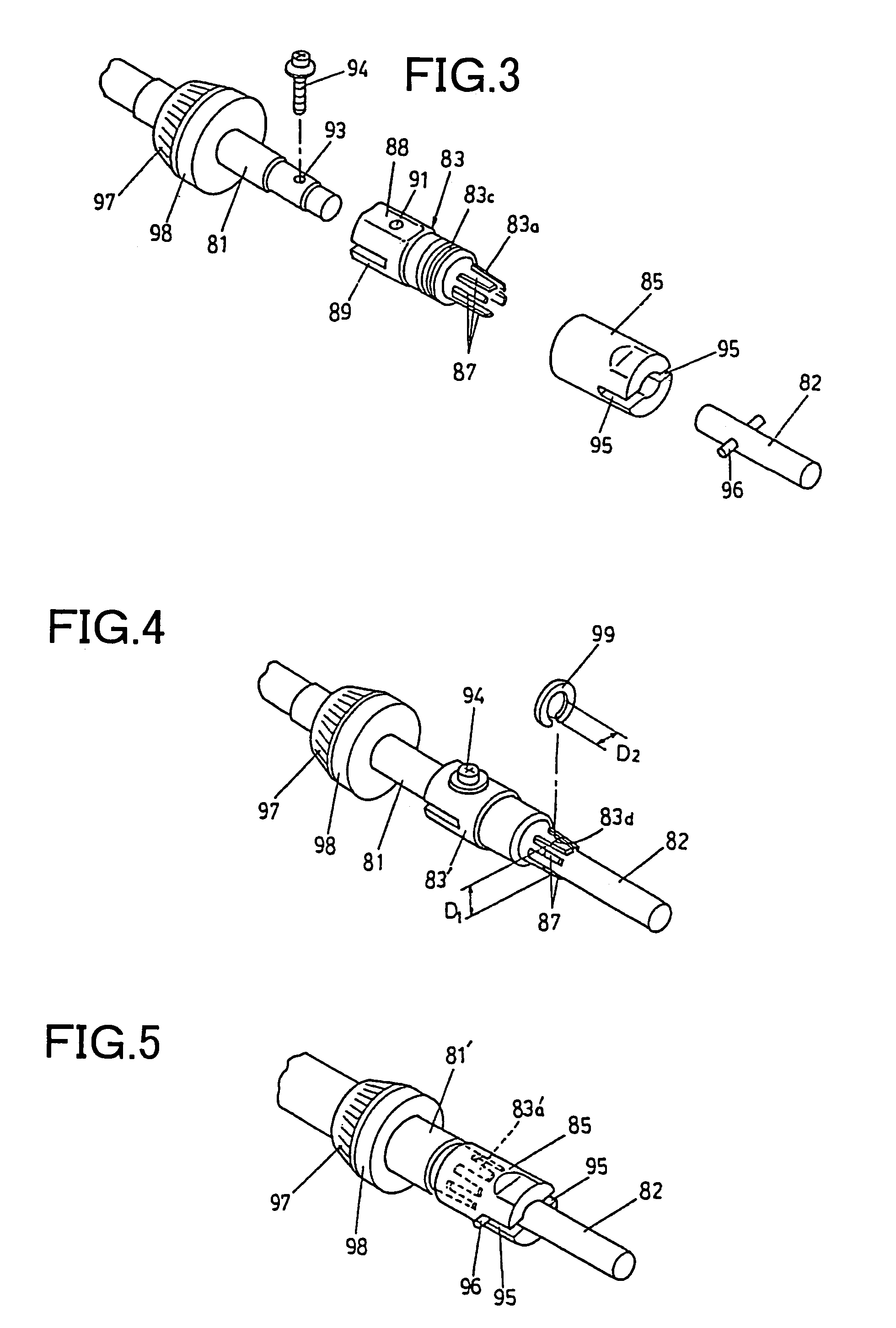
[0036]FIG. 1 is a sectional view of a first shaft and a second shaft coupled to each other by a shaft coupling device according to an embodiment of the present invention. FIG. 2 is a perspective view of the first and second shafts. FIG. 3 is an exploded perspective view of the two shafts before being coupled to each other.

[0037]The shaft coupling device couples a rotating shaft 81, which is the first shaft, with a rotating drive shaft 82, which is the second shaft. The shaft coupling device includes a grip member 83 which is a grip unit provided to the rotating shaft 81 and having a grip portion 83a on an end of the grip member to grip the rotating drive shaft 82. The shaft coupling device further includes a grip force acting member 85 which is a grip force acting unit provided to the rotating drive shaft 82 to cause a grip force for gripping the rotating drive shaft ...


PUM


Abstract

A shaft coupling device for coupling a first shaft and a second shaft together includes a grip unit to be attached to the first shaft and including a grip portion configured to grip the second shaft, the grip portion having an end with notches of a length being parallel with an axial direction of the first shaft. The shaft coupling device also includes a grip force acting unit to be attached to the second shaft and configured to cause a grip force for gripping the second shaft to act on the grip portion by moving the grip portion in a radial direction of the second shaft.

Description

CROSS-REFERENCE TO RELATED APPLICATIONS[0001]The present document incorporates by reference the entire contents of Japanese priority documents, 2003-069680 filed in Japan on Mar. 14, 2003 and 2003-308860 filed in Japan on Sep. 1, 2003.BACKGROUND OF THE INVENTION[0002]1) Field of the Invention[0003]The present invention relates to a technology for coupling a shaft to another shaft.[0004]2) Description of the Related Art[0005]In image formation apparatuses, it is required to rotate with high-precision a photosensitive member (a rotating member) carrying an image to obtain images of high-quality. In particular, rotation of high-precision is important in the tandem type full color image formation apparatus. The tandem type full color image formation apparatus includes a plurality of photosensitive members each onto which an image of a different color is formed. Each of the images formed on the photosensitive members are then transferred onto an intermediate transfer belt or a transfer s...

Claims


Application Information

Patent Timeline
Patent Type & Authority Patents(United States)
IPC IPC(8): B41F1/34G03G15/00
CPCG03G15/757G03G2221/1657G03G2215/0129
Inventor ONO, HIROSHIYOSHINO, KAORU
Owner RICOH KK
Why Eureka
Try Eureka