Adjustable impression tray with variable geometry

a technology of variable geometry and impression tray, applied in the field of dental impression tray, can solve the problems of rarely compatible solutions, inability to use two devices directly, and inability to adapt the size of the impression tray, and achieve the effect of reducing mechanical resistan

Inactive Publication Date: 2006-10-24
LIVOLSI LYDIE
View PDF14 Cites 18 Cited by
  • Summary
  • Abstract
  • Description
  • Claims
  • Application Information

AI Technical Summary

Benefits of technology

[0025]These zones of multidirectional extension make it possible to widen or tighten the impression tray, to lengthen or shorten the side branches of the gutter, or also to modify the slope of these side branches. It is thus possible, according to the description of the invention, to adapt the impression tray easily and quickly to all sizes of denture, simply by actuating the various concertina covers on the tray.
[0027]However, the tray should preferably be manufactured in disposable plastic and for single use. The tiresome stages, prior to impression-taking, cleaning and sterilization of the impression tray are thus avoided for the dentist, who will save invaluable time.
[0028]According to the description, the impression tray has the advantage of being capable of including at least one dividable zone with lower mechanical resistance. This dividable zone box makes it possible to split the impression tray into one or more sectoral impression trays.

Problems solved by technology

However, these solutions are seldom compatible with the former techniques allowing for adaptation of the size of the impression tray.
These two devices cannot be used directly.
They require preliminary working according to a long and difficult to apply process.
This process requires the use of expensive additional and specific equipment.
These devices thus are not suitable for the technical problem raised.
They only allow for limited adaptation to varying morphologies.
Moreover, they do not allow for the creation of a sectoral impression tray.
Nevertheless, devices of this type are expensive and not very practical.
They cannot generally apply to all sizes of denture.
They are, moreover, difficult to clean.
In addition, they are not designed to be split for sectoral impression trays.

Method used


Image

  • Adjustable impression tray with variable geometry
  • Adjustable impression tray with variable geometry
  • Adjustable impression tray with variable geometry

Examples


Embodiment Construction

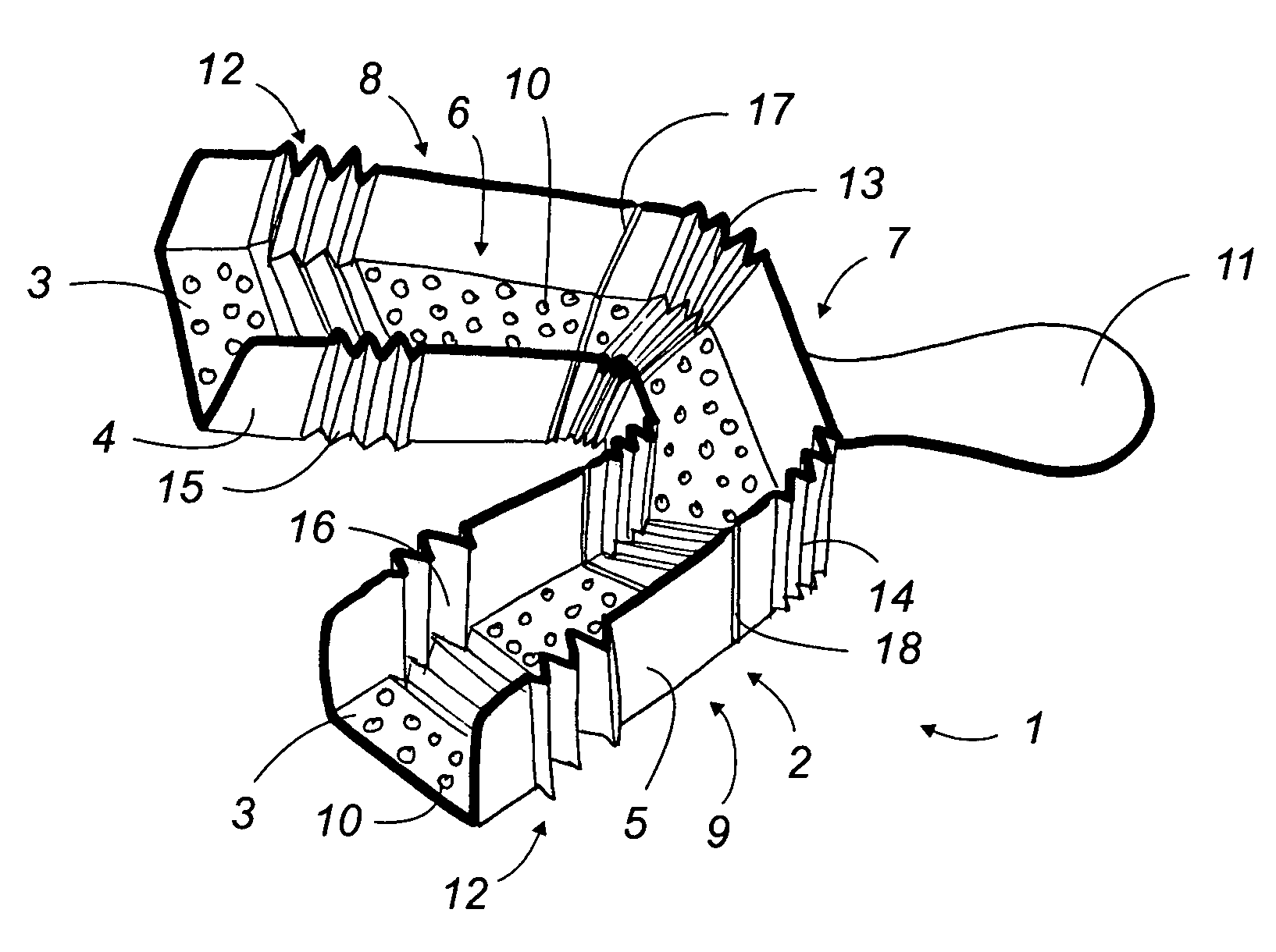
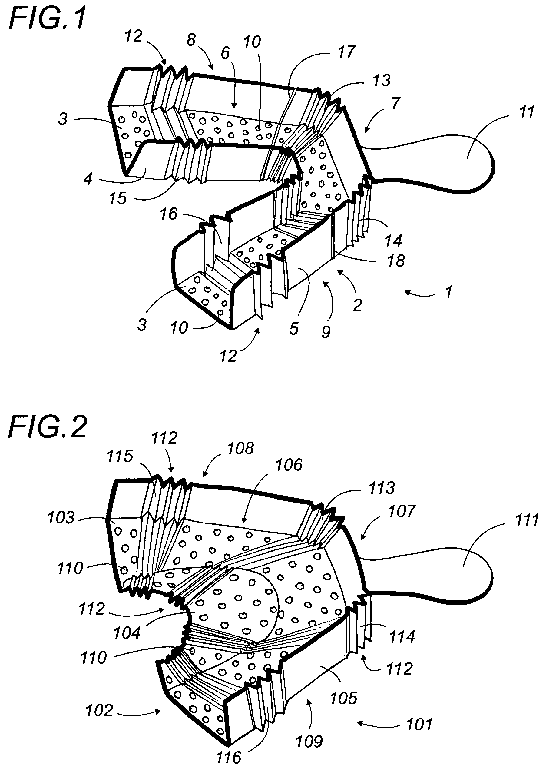
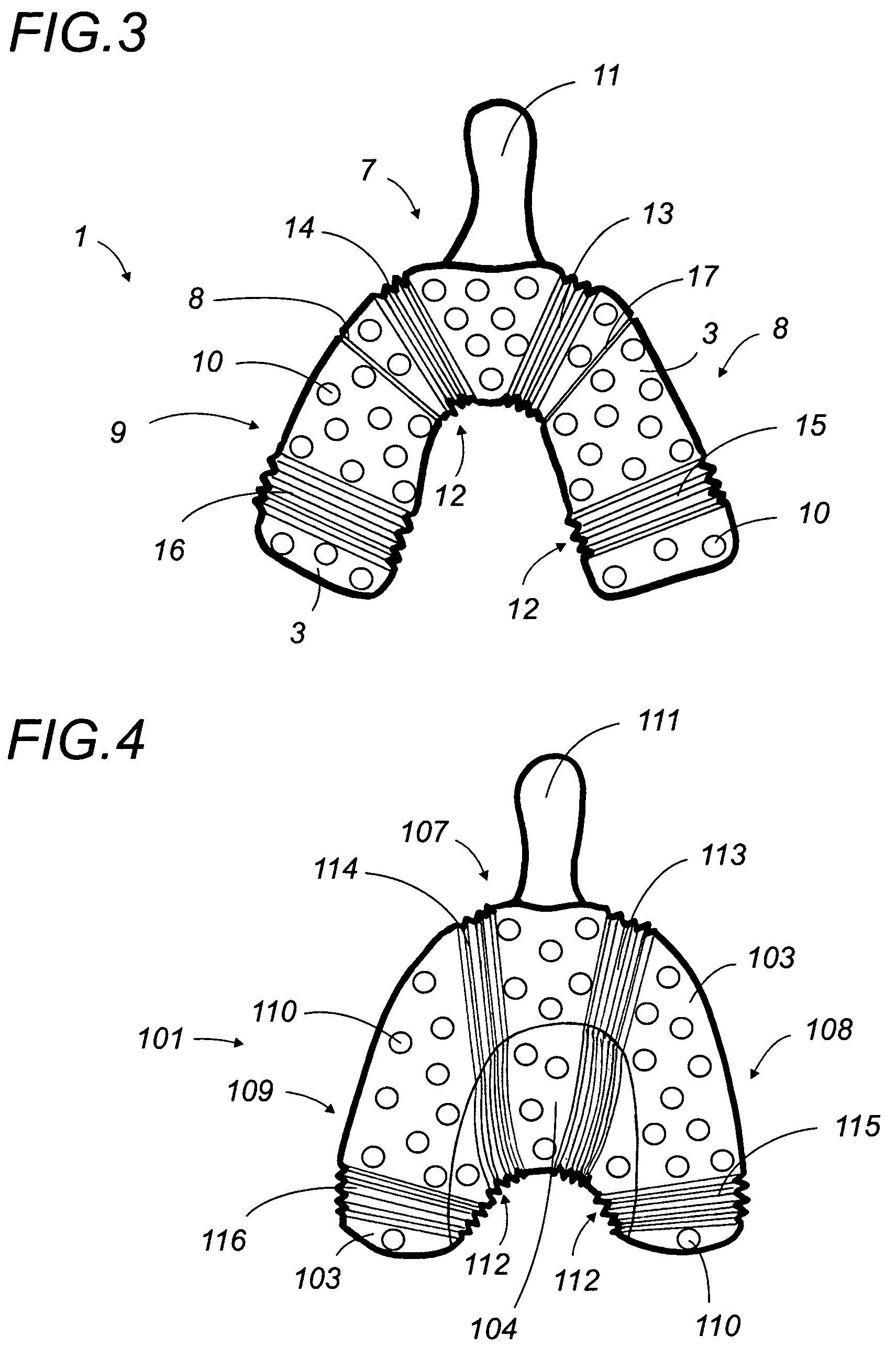
[0048]The adjustable impression tray according to the present invention will now be described in a detailed way with reference to FIGS. 1 to 17. The numbered elements provided on the various Figures will be used within the following description.

[0049]In the continuation of this description, one part will describe the “top impression tray” the impression tray intended to capture the impression of a superior dental arch. One part will describe the “bottom impression tray” the impression tray intended to capture the impression of an inferior dental arch.

[0050]In the same way, the concepts of a top or a lower face, a top part or lower part, etc. concerning the impression tray of this invention will be defined and compared to the following orientation. The defined orientation of the impression tray is when it is positioned in the mouth of the patient ready to carry out an impression.

[0051]In the various Figures, the impression trays represented correspond to preferred configurations and ...


PUM


Abstract

The invention relates to an adjustable impression tray (1) comprising a trough (2) in the form of an arch with a straight central portion (7) extended by two lateral branches (8,9), essentially matching the form of a dental arch and comprising several integral zones which may be deformed at the temperature of use in the form of a multi-directional extension means (12), for example an accordion-like bellows arrangement (13 to 16). The impression tray, preferably for single usage, advantageously comprises splitting zones (17, 18) which allow the production of impression trays of differing sectors, which by comprising one or several deformation zones are equally adjustable. The invention is of interest to dentists and prosthetic dentists and more generally to producers and users of dental equipment.

Description

[0001]This application is a National Stage completion of PCT / FR2003 / 001199 filed Apr. 15, 2003, which in turn claims priority from French Patent Application Ser. No. 02 / 04699 filed Apr. 15, 2002.FIELD OF INVENTION[0002]The present invention relates to a dental impression tray of adjustable size intended mainly for dentistry.TECHNOLOGICAL BACKGROUND TO THE INVENTION[0003]In the field of dentistry, it is often necessary to manufacture and install prostheses. These refer to bridges and, dental apparatuses of various types or similar. Prior to the manufacture of these prostheses, it is essential to take an impression of the denture of the patient. This impression makes it possible to subsequently manufacture a dental prosthesis with specific measurements in a laboratory.[0004]For this purpose, the expert uses a device called an impression tray. This is made of a gutter approximately in the shape of a horseshoe and which matches the shape of a dental arch. The dentist fills this gutter w...

Claims


Application Information

Patent Timeline
Patent Type & Authority Patents(United States)
IPC IPC(8): A61C9/00
CPCA61C9/0006
Inventor LIVOLSI, LYDIE
Owner LIVOLSI LYDIE
Why Eureka
Try Eureka