Precision wideband 50 Ohm input and 50 Ohm output or 100 Ohm output differential reflection bridge

Inactive Publication Date: 2006-10-24
ANRITSU CORP
View PDF5 Cites 27 Cited by
  • Summary
  • Abstract
  • Description
  • Claims
  • Application Information

AI Technical Summary

Benefits of technology

[0017]According to the present invention a measuring device is provided that uses a true 100 Ohm differential bridge that is not compromised by the translation from 50 to 100 Ohms through a non-ideal transformer. The measuring device although providing measureme

Problems solved by technology

The balanced transformer approach, however, has limitations due to the need of a broad band 1:√2 turns ratio.
Th

Method used


Image

  • Precision wideband 50 Ohm input and 50 Ohm output or 100 Ohm output differential reflection bridge
  • Precision wideband 50 Ohm input and 50 Ohm output or 100 Ohm output differential reflection bridge
  • Precision wideband 50 Ohm input and 50 Ohm output or 100 Ohm output differential reflection bridge

Examples


Embodiment Construction

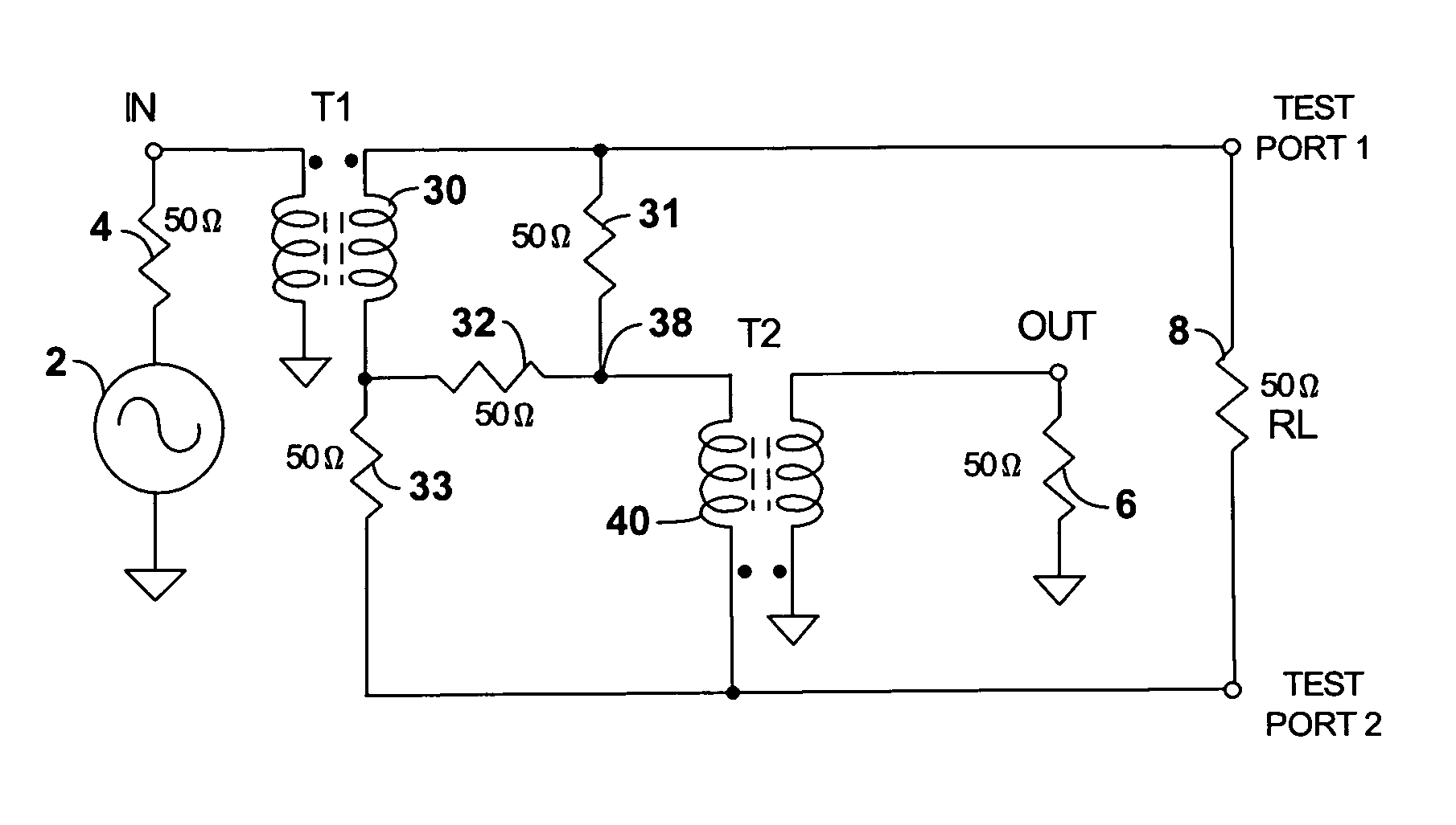
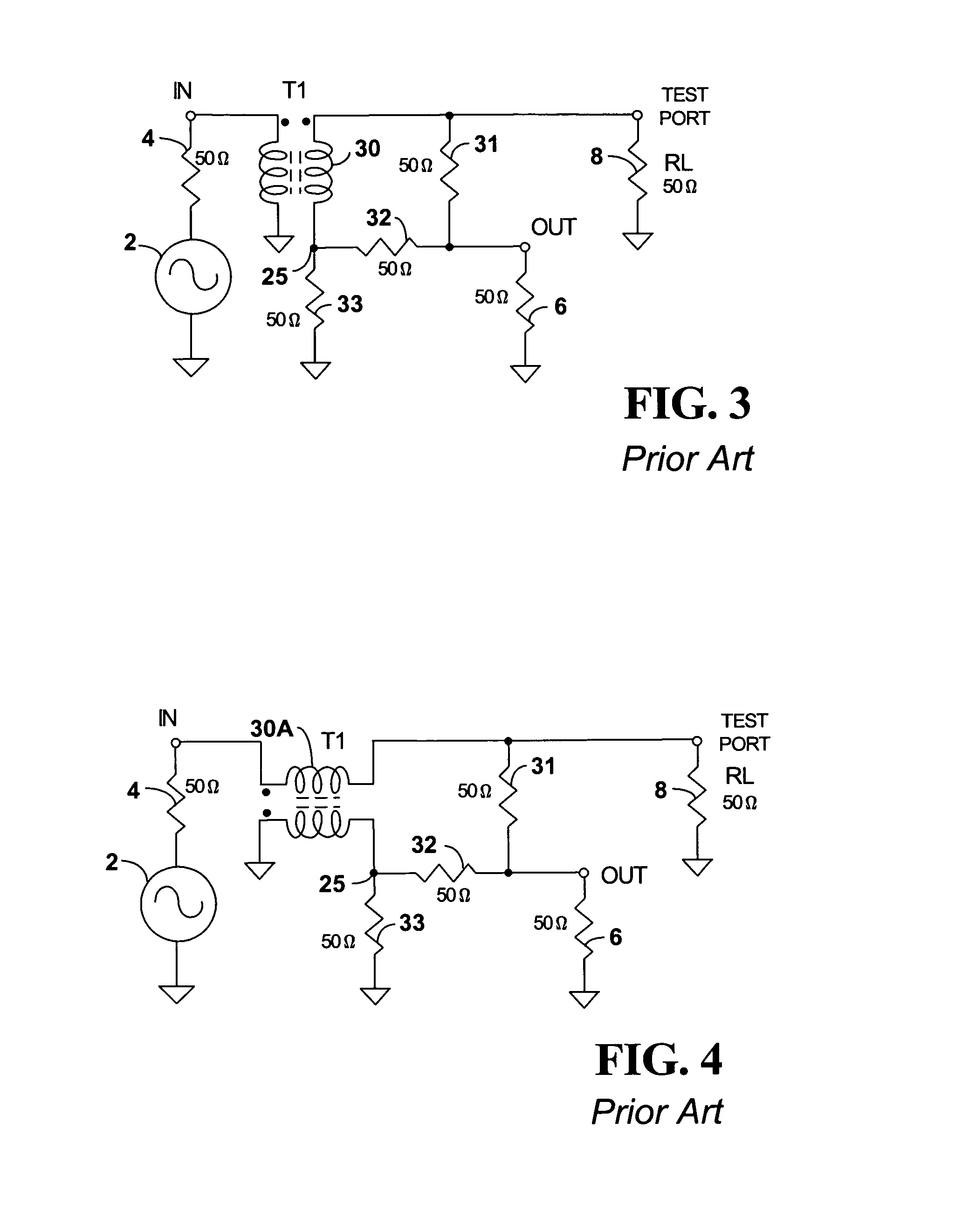
[0037]FIG. 5 shows a differential measurement bridge according to embodiments of the present invention. The bridge includes 50 Ohm resistors 31–33 similar to the resistive bridge of FIG. 3. A T1 transformer 30 couples a signal source 2 and resistor 4 to the resistors 31–33. A resistor 6 connects a measurement output OUT to ground, similar to FIG. 3.

[0038]FIG. 5 according to the present invention, and in contrast with FIG. 3, further includes a second transformer labeled T2. The T2 transformer 40 has a first winding connecting from the output node OUT to ground. A second winding connects a node 38 between resistors 31 and 32 to a second test port TEST PORT 2. The second test port TEST PORT 2 replaces the ground connection of FIG. 3. The second test port TEST PORT 2 is also connected to the resistor 33 and the 50 Ohm RL load resistor 8. This allows RL to be measured differentially directly, rather than through single ended measurements. RL also now has no path to ground, making it imm...


PUM


Abstract

A differential reflection bridge is provided for a 100 Ohm load, the bridge not being compromised by a translation to a 50 Ohm system. The reflection bridge uses two transmission line baluns. The first traditional balun T1 connects the input signal source to a resistor bridge. The second balun T2 connects between a central node of the resistor bridge and an output OUT as well as a second test port that eliminates a path to ground. With no ground path the bridge is immune to common mode impedance disturbances.

Description

BACKGROUND[0001]1. Technical Field[0002]The present invention relates to making differential impedance measurements of a resistive device using a reflection bridge. More particularly, the present invention relates to a reflection bridge providing for differential measurements of both 50 Ohm and 100 Ohm complex impedances.[0003]2. Related Art[0004]Conventional differential measurement systems for measuring 100 Ohm components included balanced 100 Ohm transmission lines. Characterization of components was provided using multiple single port measurements. The balanced parameters were extracted from at least two single ended measurements.[0005]FIG. 1 shows a conventional differential bridge used to make differential measurements by obtaining two single ended measurements. The test system includes a signal source 2 connected through a 50 Ohm line 4 to provide an input. A resistive load 8, labeled R1, and resistive load 9, labeled R2, are each connected to one of two test ports TEST PORT ...

Claims


Application Information

Patent Timeline
IPC IPC(8): G01R27/28
CPCG01R27/04
Inventor BRADLEY, DONALD ANTHONY
Owner ANRITSU CORP
Why Eureka
Try Eureka