Data input devices and methods for detecting movement of a tracking surface by detecting laser doppler self-mixing effects of a frequency modulated laser light beam

a data input device and laser light beam technology, applied in the field of computer input devices, can solve the problems of devices that cannot devices that still require one moving part, cursor to skip, devices that lack the ability to track on any surface,

Inactive Publication Date: 2006-10-24
MICROSOFT TECH LICENSING LLC
View PDF82 Cites 34 Cited by
  • Summary
  • Abstract
  • Description
  • Claims
  • Application Information

AI Technical Summary

Problems solved by technology

But such devices lack the ability to track on any surface, requiring a suitable frictional interface between the ball and the surface.
Moreover, these devices still require one moving part, the ball.
In addition, aliasing artifacts may cause the cursor to skip, rather than move fluidly during rapid motion of the device.
Although such devices are able to eliminate the moving ball, they are less universal by requiring a specific tracking surface to operate.
However, smooth or glossy surfaces may prove difficult to track upon, because they may generate no shadows from texture and present a low contrast image that may not provide adequate features upon which to track.
Such systems suffer from several drawbacks.
For example, such systems do not track the actual location information relating to the location of the user's moving hand and finger with respect to the device, but instead merely rely upon merely directional information to indicate the direction of cursor movement on the display and force information to indicate the proportional speed of cursor movement on the display.
These systems may be difficult to use for some users because they function solely on direction and force information, rather than position information, as is typical with a standard mouse, with which most users are accustomed and may find more intuitive.
In addition, such systems may suffer from cursor drift, wherein no finger engages the post, but one or more of the force sensors incorrectly senses a pressure.
Cursor drift is undesirable because the cursor moves across the display, without direction by the user.
Utilizing a separate laser for each tracking direction is undesirable because of the additional hardware cost and packaging required for an additional laser or lasers.

Method used


Image

  • Data input devices and methods for detecting movement of a tracking surface by detecting laser doppler self-mixing effects of a frequency modulated laser light beam
  • Data input devices and methods for detecting movement of a tracking surface by detecting laser doppler self-mixing effects of a frequency modulated laser light beam
  • Data input devices and methods for detecting movement of a tracking surface by detecting laser doppler self-mixing effects of a frequency modulated laser light beam

Examples


Embodiment Construction

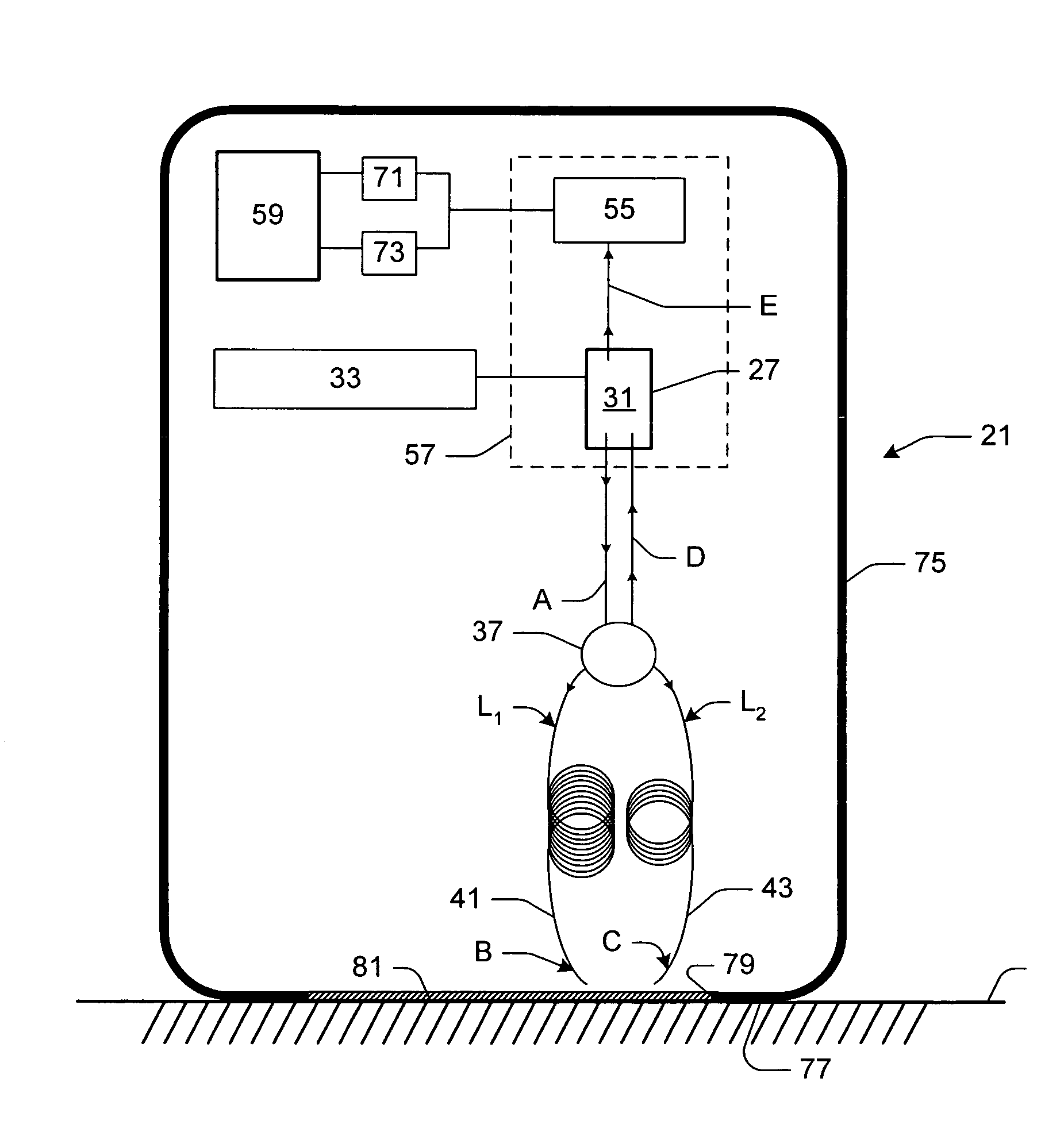
[0030]In one embodiment, the invention includes a data input device for use with a tracking surface that is optically rough, or in other words, has light-scattering properties with respect to the device, to track relative movement between the device and the tracking surface. FIG. 1 is a schematic of such a data input device, generally indicated 21, and tracking surface 25 of the present invention. The data input device 21 comprises a single laser 27 having a cavity 31 for projecting a light beam A. The data input device 21 further comprises a light beam modulator 33 for modulating the frequency of the light beam A over time (e.g., FIG. 7). In one example, the light beam modulator 33 modulates the light beam A in a time-based pattern, such as the triangular time-based pattern depicted in FIG. 7. In one example, the light beam modulator 33 comprises a current modulator for modulating the current supplied to the single laser 27. By modulating the current of the laser 27, the frequency ...


PUM


Abstract

A data input device for use with a tracking surface having light-scattering properties with respect to the device. The device comprising a single laser having a modulated light beam. A beam splitter splits the modulated light beam into two light beams projected along separate paths toward the tracking surface. A portion of the light striking the tracking surface reflects back into a cavity of the single laser for self-mixing with the projected light, thereby altering first and second characteristics of the projected modulated light beam according to first and second directions associated with the tracking surface. A detector associated with the laser detects the altered first and second characteristics of the modulated light beam projected by the laser, and a controller responsive to the detector determines the relative movement of the tracking surface and data input device relative to one another as a function of the altered first and second characteristics detected by the detector.

Description

TECHNICAL FIELD[0001]Embodiments of the present invention relate to the field of computer input devices, and particularly data input devices, such as a mouse, trackball, joystick, touch pad, or a touch-sensitive post. In particular, embodiments of this invention relate to data input devices for use with a tracking surface having light-scattering properties, the device comprising a single laser having a cavity from which a light beam is projected, a light beam modulator for modulating the frequency of the light beam over time, a beam splitter for splitting the modulated light beam into a first modulated light beam projected along a first light path and a second modulated light beam projected along a second light path, reflections of the light beams altering respective first and second characteristics of the projected modulated light beam, a detector associated with the laser for detecting the altered first and second characteristics, and a controller responsive to the detector for de...

Claims


Application Information

Patent Timeline
Patent Type & Authority Patents(United States)
IPC IPC(8): G09G5/00
CPCG01P3/366G06F3/03543G06F3/03544G06F3/03547G06F3/042
Inventor JIANPING, XIEHAI, MINGTIANPENG, ZHAOLIANG, LVHUAQIAO, GUIKONG, YUANRANTA, CRAIG S.
Owner MICROSOFT TECH LICENSING LLC
Why Eureka
Try Eureka