Optical record carrier, drive unit, data updating method and software version-up method

a technology of optical record carrier and drive unit, applied in the field of optical record carrier, can solve the problems of inability to efficiently record data in a finite record area of a disc, inability to accurately record and reproduce actions, and large drive, so as to prevent cross talk, facilitate manufacturing, and prevent unauthorized copying

Inactive Publication Date: 2006-10-24
HITACHT MAXELL LTD
View PDF11 Cites 9 Cited by
  • Summary
  • Abstract
  • Description
  • Claims
  • Application Information

AI Technical Summary

Benefits of technology

[0011]The disc may be configured such that a manufacturer formats the one of the first and second areas, which has been assigned the read only area, while a user formats the other which has been assigned the recordable area. Then, a specific format which the manufacturer may usually form (for example, using pits) is arranged in the read only area, successfully prohibiting the user from copying data from the read only area, and contributing to prevention of unauthorized copying. In other words, a format for the read only area and a format for the recordable area may be different from each other. Where the disc is used such that software is stored in the one which is assigned the read only area, and the result of use of the software is stored in the other which is assigned the recordable area, a user of the optical record carrier does not have to additionally purchase a dedicated memory device (e.g., a memory card) for storing the result of the software (e.g., game software).
[0012]The first area has sequential address numbers provided from the inner side on the disc, while the second area has sequential address numbers provided from the outer side on the disc. The first and second areas are thus independently addressed. Since the recordable area is independent of the read only area, a disc control area including recording data, exchange data and other data in the recordable area is determined irrespective of the read only area and the re

Problems solved by technology

However, this would change addresses in the RAM area depending upon a length of ROM data and disadvantageously make undefined disc's control area that stores exchange and other information, resulting in the unstable recording and reproducing actions.
In addition, without the prefixed capacity of the ROM

Method used


Image

  • Optical record carrier, drive unit, data updating method and software version-up method
  • Optical record carrier, drive unit, data updating method and software version-up method
  • Optical record carrier, drive unit, data updating method and software version-up method

Examples


Embodiment Construction

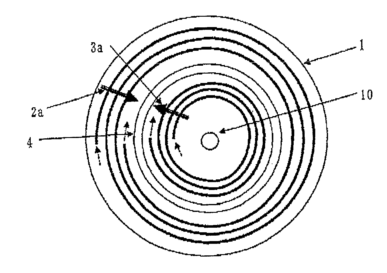
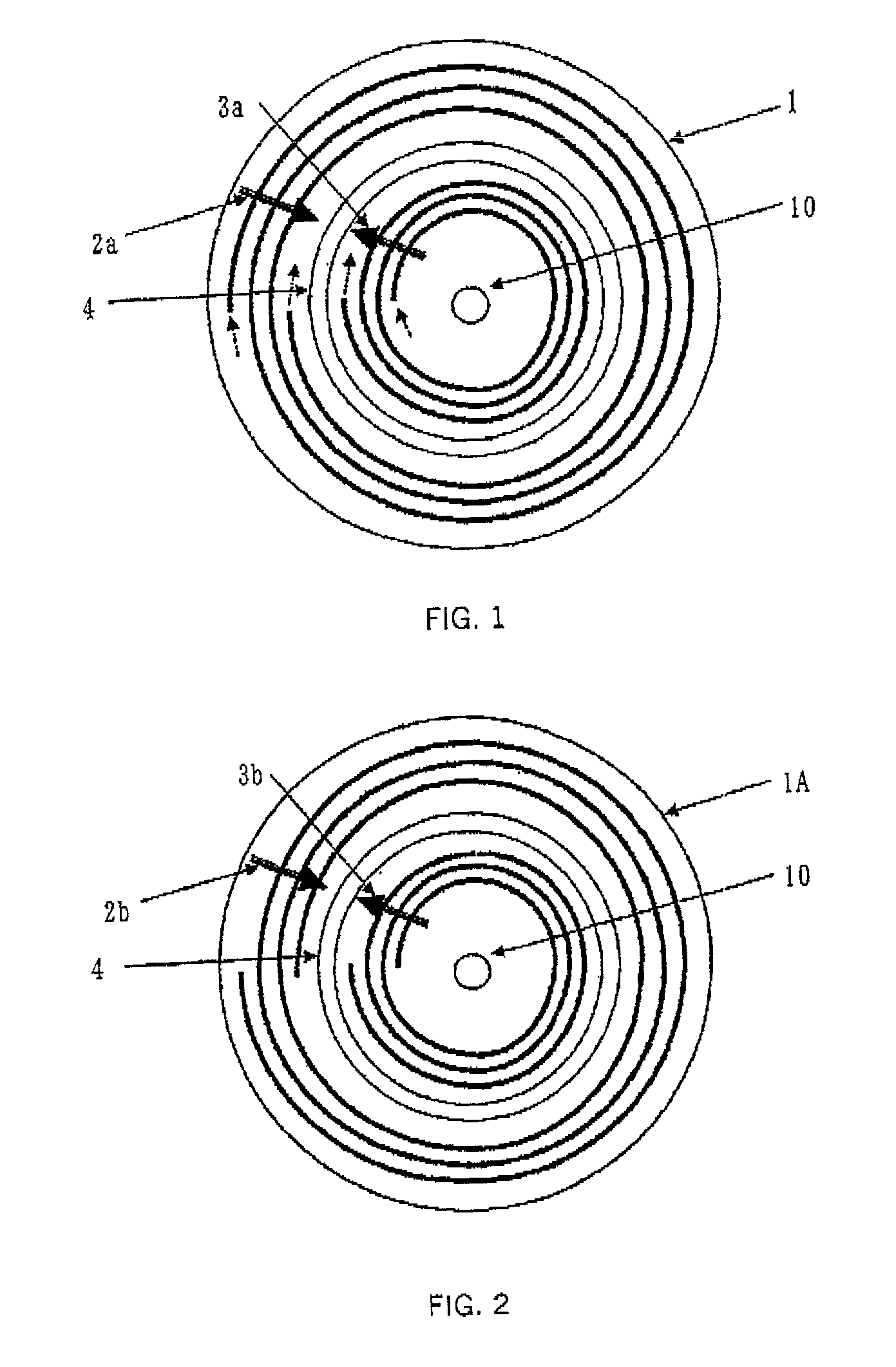
[0027]Referring to FIG. 1, a description will now be given of an optical disc 1 as optical record carrier of the instant embodiment. Here, FIG. 1 is a schematic plane view of the optical disc 1. The optical disc 1 includes, around a center hole 10, a record area 2 having a spiral track 2a as a record unit, a record area 3, at the inner side the record area 2, which has a spiral track 3a extending in a direction reverse to the track 2a, and a buffer area 4 between the record areas 2 and 3.

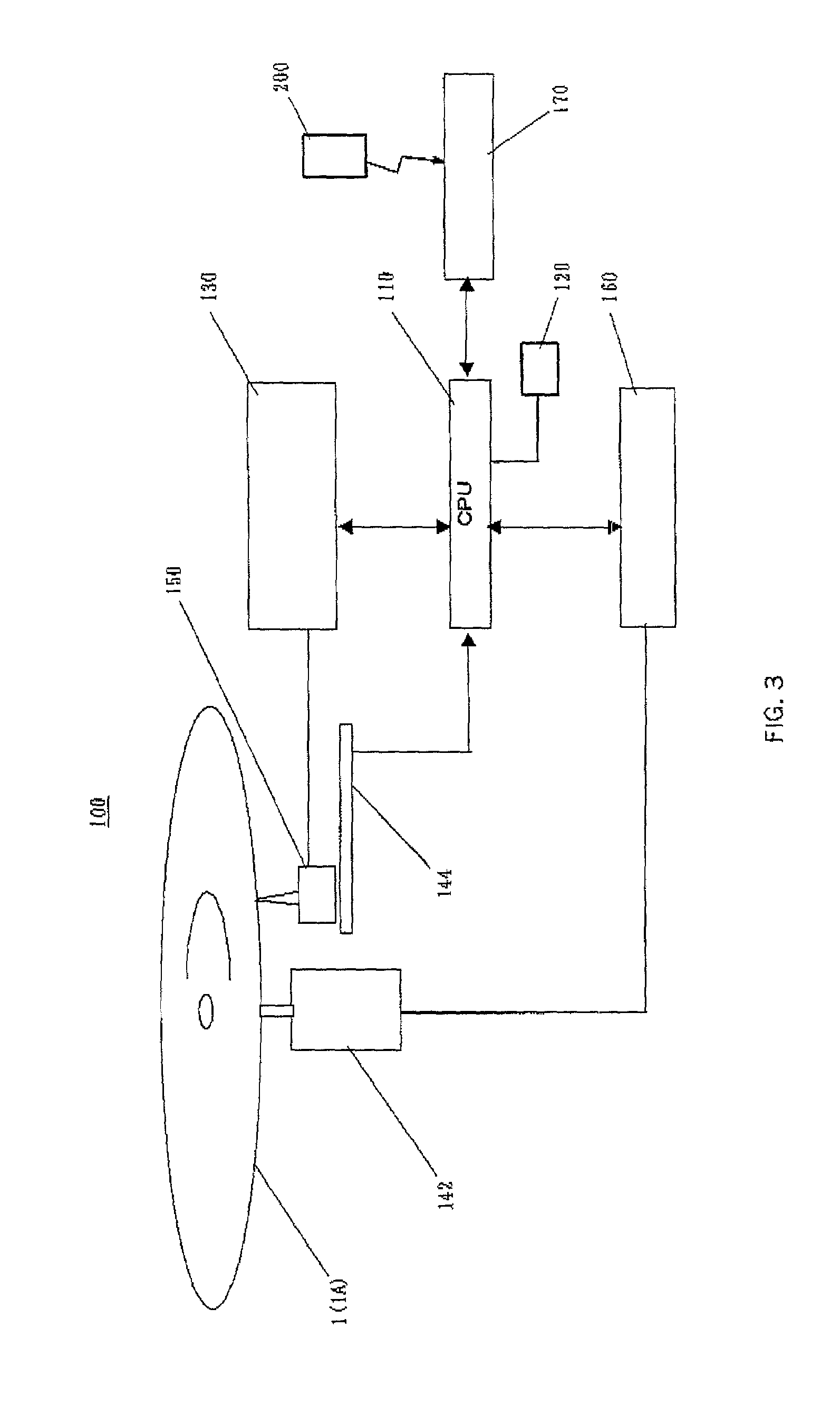
[0028]Suppose that an optical head 150 in a drive 100 for driving the optical disc 1, which will be described later, is located above the optical disc 1. It is understood that as the optical disc 1 rotates counterclockwise viewed from the optical head 150, a record position in the record area 3 (or a position of the optical head 150) moves toward the outer side on the disc 1 while a record position in the record area 2 moves toward the inner side. Thus, the optical disc 1 is configured such that the...


PUM


Abstract

A disc-shaped optical record carrier includes a first area having a spiral track extending in a first direction from an inner side on the disc, and a second area having a spiral track extending in a second direction opposite to the first direction, from an outer side on the disc located on the same plane as the first area on the disc, wherein one of the first and second areas is assigned a recordable area and the other is assigned a read only area.

Description

BACKGROUND OF THE INVENTION[0001]The present invention relates generally to record carriers to be recorded and / or reproduced by optical means, and drive units for driving the record carriers, and more particularly to a disc-shaped record carrier having a characterized record structure or format, and a drive unit for recording and / or reproducing the record carrier. The present invention is suitable, for example, for an optical disc that includes both a read only (referred to as “ROM” hereinafter) area that allows a reproduction of prerecorded data, and a recordable (referred to as “RAM” hereinafter) area that may record new or additional data.[0002]Optical discs, spread as an optical record carrier, include ROM media, such as a CD-ROM and a DVD (Digital Versatile Disc), write-once CD-Rs, other various magneto-optical record carriers, and phase change record carriers, such as a DVD-RAM. Along with the recent developing information industry, demands to optical record carriers have rang...

Claims


Application Information

Patent Timeline
IPC IPC(8): G11B7/24G06F3/06G06F9/445G11B7/007G11B20/12
CPCG06F3/0677G06F8/65G11B7/007G11B20/1217G06F3/0607G06F3/0644G11B2020/1247G11B2020/1248G11B2020/1267G11B2220/211G11B2220/2525
Inventor IIDA, TAMOTSU
Owner HITACHT MAXELL LTD
Why Eureka
Try Eureka