Surveying instrument

a technology of instrument and measurement point, applied in the field of surveying instruments, can solve the problems of difficult to continuously acquire the image during the change process, and difficulty in acquiring data by quickly changing the measuring point,

Inactive Publication Date: 2006-10-31
KK TOPCON
View PDF14 Cites 65 Cited by
  • Summary
  • Abstract
  • Description
  • Claims
  • Application Information

AI Technical Summary

Problems solved by technology

Further, the conventional type automatic surveying instrument performs surveying operation by collimating the measuring point one by one, and it is difficult to acquire the data by quickly changing the measuring point.
When the measuring point is changed, it is impossible to continuously acquire the image during the process of change.
The surveying operator must go up each time to a point where the automatic surveying instrument is installed, and it has been inconvenience.

Method used


Image

  • Surveying instrument
  • Surveying instrument
  • Surveying instrument

Examples


Embodiment Construction

[0025]Description will be given below on embodiments of the present invention referring to the drawings.

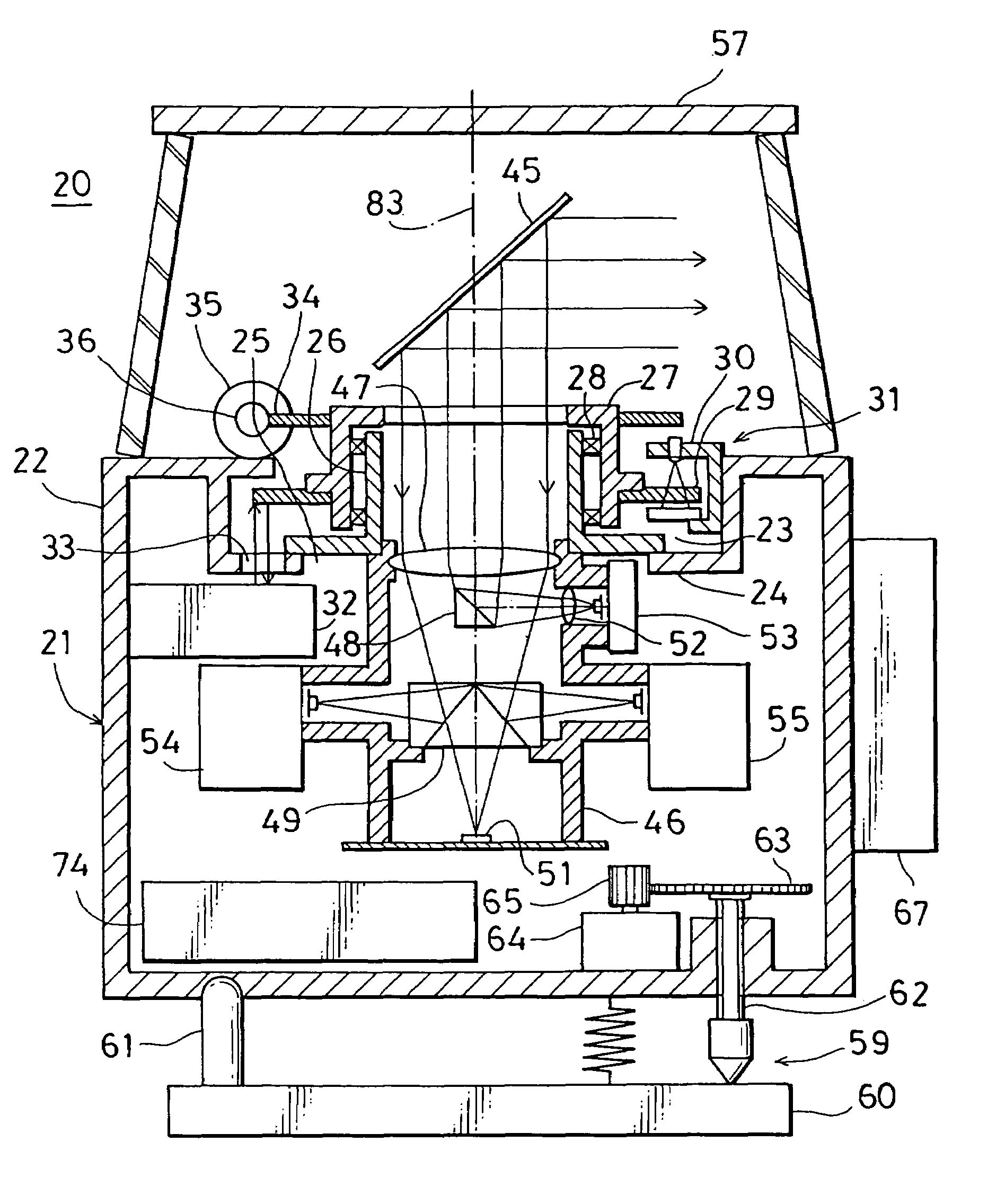
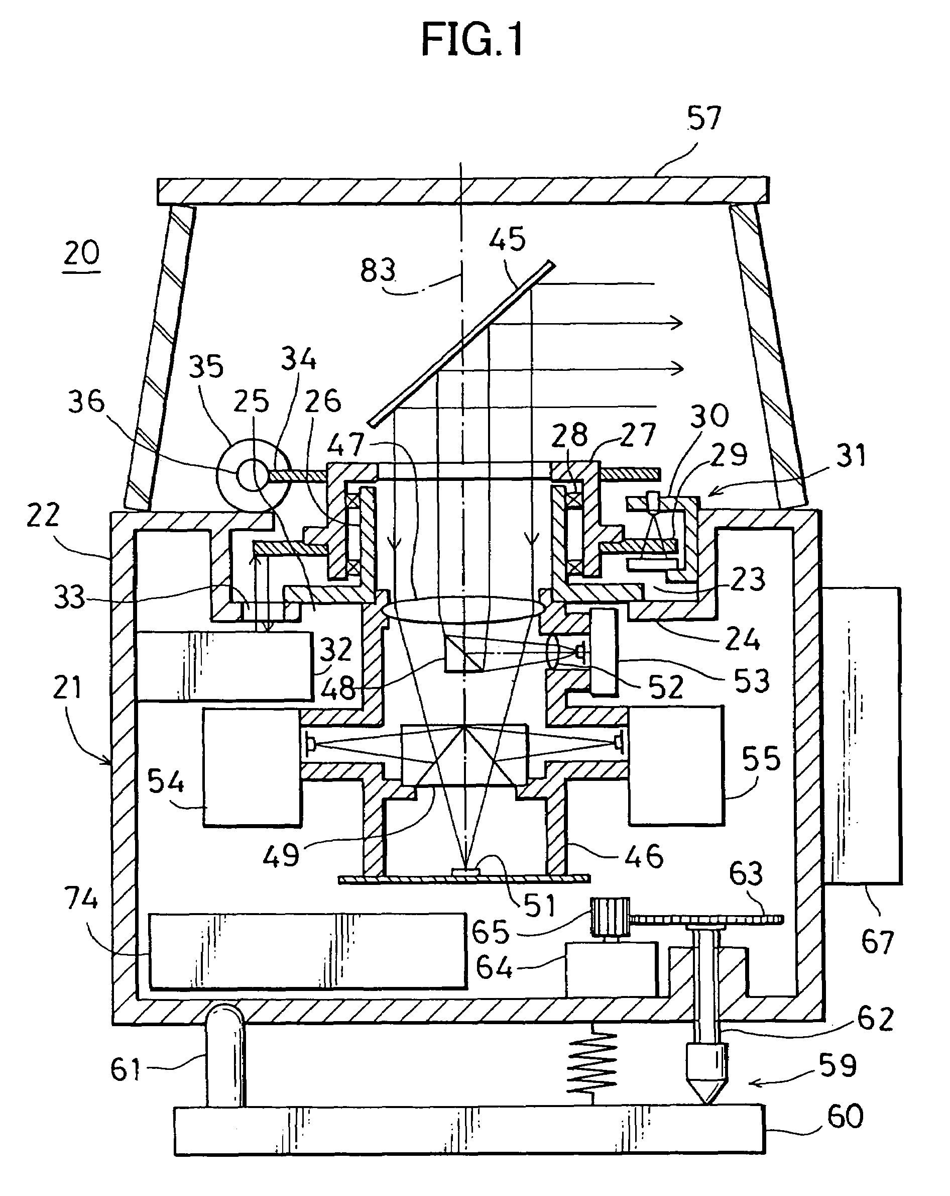
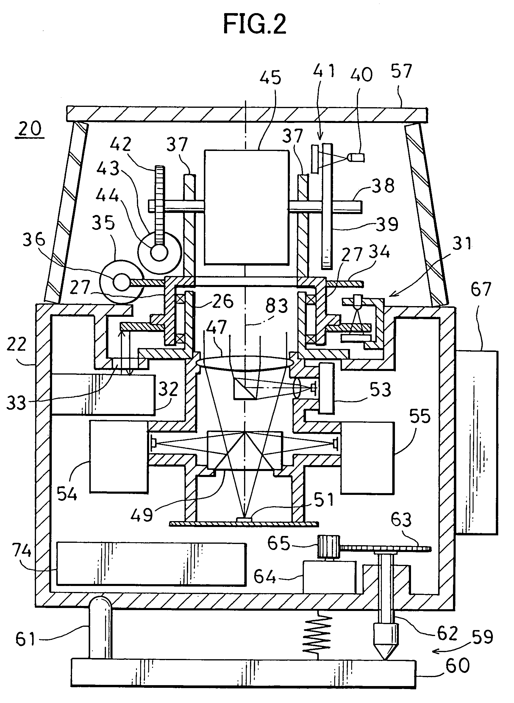
[0026]A surveying instrument 20 comprises a surveying instrument main unit 21, a leveling unit 59, and an operation device 67 removably mounted on a main unit case 22.

[0027]First, the surveying instrument main unit 21 will be described.

[0028]A recessed portion 23 is formed on an upper surface of the main unit case 22. On the recessed portion 23, a hole 25 is formed so that a flange 24 is provided around it. A flanged hollow shaft 26 is mounted in the flange 24 concentrically with the hole 25, and a rotating unit 27 is rotatably engaged on the flanged hollow shaft 26 via bearings 28. On the rotating unit 27, a pattern ring 29 for an encoder is arranged perpendicularly to a rotation shaft of the rotating unit 27. A detector 30 is provided on an inner peripheral wall surface of the recessed portion 23 to face the pattern ring 29. The detector 30 and the pattern ring 29 make up togeth...


PUM


Abstract

The present invention provides a surveying instrument (20), comprising a surveying instrument main unit (21) which projects a measuring light to an object to be measured and measures a position based on a reflection light from the object to be measured and an operation device (67) which is removably attached on the surveying instrument main unit, wherein the surveying instrument main unit comprises a distance measuring unit (54) and (55) for emitting the measuring light and for measuring a distance, an image pickup unit (51) and (53) for acquiring an image, a reflection mirror (45) rotatably mounted and used for directing the measuring light toward the object to be measured, for directing the reflected light from the object to be measured toward a light receiving unit, and for directing the image in a projecting direction toward the image pickup unit, a detecting means (31) for detecting a rotating position of the reflection mirror, and a control unit (74) for controlling at least the distance measuring unit, the image pickup unit and the rotating position of the reflection mirror, and wherein the operation device comprises a display unit for displaying the image acquired by the image pickup unit.

Description

FIELD OF THE INVENTION[0001]The present invention relates to a surveying instrument capable of measuring a distance to a point of measurement target and of acquiring an image.BACKGROUND ART[0002]As a device for automatically measuring a position of a measurement target, an automatic surveying instrument has been known in the past, which comprises an automated total station comprising a distance measuring unit.[0003]Referring to FIG. 7, description will be given below on a conventional type automatic surveying instrument.[0004]A base unit 2 is disposed on a leveling unit 1. A frame unit 4 is mounted on the base unit 2 via a horizontal rotation shaft 3 so that it can be rotated in a horizontal direction. A body tube 6 is mounted on the frame unit 4 via a vertical rotation shaft 5 so that it can be rotated in a vertical direction.[0005]A horizontal rotation gear 7 is mounted on the horizontal rotation shaft 3, and a horizontal rotating motor 8 is mounted on the base unit 2. A horizonta...

Claims


Application Information

Patent Timeline
Patent Type & Authority Patents(United States)
IPC IPC(8): G01C15/00
CPCG01C15/002
Inventor KUMAGAI, KAORUOHTOMO, FUMIO
Owner KK TOPCON
Why Eureka
Try Eureka