Surveying Instrument And Three-Dimensional Camera

a three-dimensional camera and scanning instrument technology, applied in the field of scanning instruments, can solve the problems of high cost, complicated structure of laser scanners, large size, etc., and achieve the effect of simple structure, easy acquisition of point cloud data, and simple structur

Active Publication Date: 2016-08-18
KK TOPCON
View PDF2 Cites 43 Cited by
  • Summary
  • Abstract
  • Description
  • Claims
  • Application Information

AI Technical Summary

Benefits of technology

[0004]It is an object of the present invention to provide a simple and low cost surveying instrument capable of acquiring a point cloud data and further to provide a simple and low cost three-dimensional camera capable of acquiring an image with a three-dimensional data.

Problems solved by technology

Such laser scanner has a complicated structure and is expensive.
However, such surveying instrument also has a complicated structure and is a large size and expensive.

Method used


Image

  • Surveying Instrument And Three-Dimensional Camera
  • Surveying Instrument And Three-Dimensional Camera
  • Surveying Instrument And Three-Dimensional Camera

Examples


Embodiment Construction

[0026]A description will be given below on an embodiment of the present invention by referring to the attached drawings.

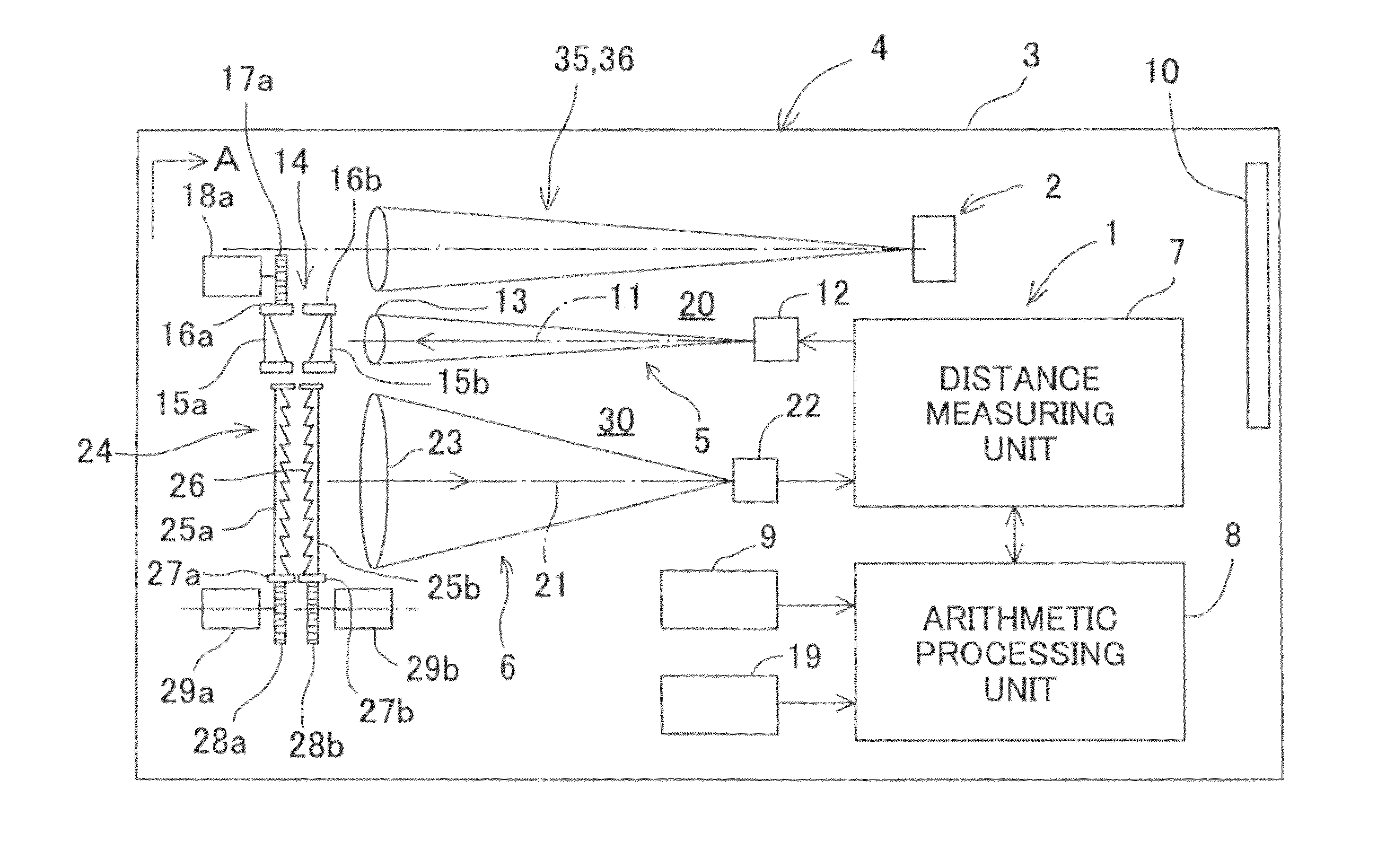
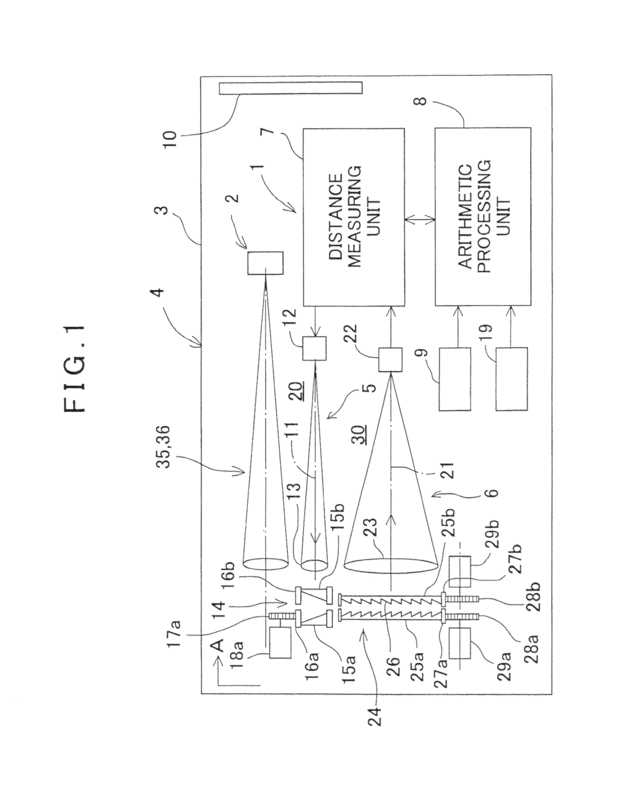
[0027]FIG. 1 is a schematical diagram to show a surveying instrument and a three-dimensional camera comprising the surveying instrument according to the embodiment of the present invention.

[0028]In FIG. 1, reference numeral 1 denotes a surveying instrument, reference numeral 2 denotes an image pickup device and reference numeral 3 denotes a case for accommodating the surveying instrument 1 and the image pickup device 2. The surveying instrument 1 and the image pickup device 2 integrally make up a three-dimensional camera 4. The case 3 may be installed on a tripod or may be portable (handheld).

[0029]First, a description will be given on the surveying instrument 1.

[0030]The surveying instrument 1 has a distance measuring light projecting unit 5, a light receiving unit 6, a distance measuring unit 7, an arithmetic processing unit 8, a projecting direction detecting un...


PUM


Abstract

The invention provides a surveying instrument, which comprises a light emitting element for emitting a distance measuring light, a distance measuring light projecting unit for projecting the distance measuring light, a light receiving unit for receiving a reflected distance measuring light, a photodetection element for receiving the reflected distance measuring light and for producing a photodetection signal and a distance measuring unit for performing a distance measurement based on a light receiving result from the photodetection element, further comprises a first optical axis deflecting unit disposed on a projection optical axis of the distance measuring light for deflecting an optical axis of the distance measuring light at a deflection angle as required and in a direction as required, a second optical axis deflecting unit disposed on a light receiving optical axis for deflecting the reflected distance measuring light at the same deflection angle and in the same direction as the first optical axis deflecting unit and a projecting direction detecting unit for detecting a deflection angle and a deflecting direction by the first optical axis deflecting unit, wherein it is so arranged that the distance measuring light is projected through the first optical axis deflecting unit and the reflected distance measuring light is received by the photodetection element through the second optical axis deflecting unit and a three-dimensional data of a measuring point is obtained based on a distance measuring result of the distance measuring unit and a detection result of the projecting direction detecting unit.

Description

BACKGROUND OF THE INVENTION[0001]The present invention relates to a surveying instrument capable of easily acquiring a point cloud data and a three-dimensional camera capable of acquiring an image and an image with a three-dimensional data.[0002]There is a laser scanner as a surveying instrument capable of acquiring the point cloud data, the laser scanner scans a distance measuring light as projected in a vertical direction and a horizontal direction by a deflecting mirror rotatable in the vertical direction and a deflecting mirror rotatable in the horizontal direction, and acquires the point cloud data.[0003]Such laser scanner has a complicated structure and is expensive. Further, there is a surveying instrument including an image acquiring device together with a laser scanner and acquiring an image at the same time as acquiring the point cloud data and capable of acquiring an image with the three-dimensional data. However, such surveying instrument also has a complicated structure...

Claims


Application Information

Patent Timeline
Patent Type & Authority Applications(United States)
IPC IPC(8): G01C3/08H04N13/02G01S17/86G01S17/89
CPCG01C1/04G01C3/08H04N13/025G01S17/89G01S7/4817G01C15/002G01S17/86H04N13/25
Inventor OHTOMO, FUMIOKUMAGAI, KAORU
Owner KK TOPCON
Why Eureka
Try Eureka