
Survey system

a technology of a surveillance system and a detection system, applied in the field of surveillance systems, can solve the problem that the collimation target b>3/b> cannot be properly found

Inactive Publication Date: 2005-11-17
SOKKOIA COMPANY LIMITED
View PDF1 Cites 47 Cited by
  • Summary
  • Abstract
  • Description
  • Claims
  • Application Information

AI Technical Summary

Benefits of technology

"The present invention provides a survey system that can search for proper guide light even when there is disturbing light or noise light in the environment. The system uses a recursion reflector and a direction detector to automatically align the telescope with the guide light. The system also has a light-receiving-direction changing means that can rotate the direction detector to a position that is outside of the light receiving range of the disturbing light. This allows the system to restart the search for guide light and properly align the telescope with the target. The technical effect of this invention is to improve the accuracy and efficiency of surveying and to enhance the reliability of the survey system."

Problems solved by technology

Therefore, even if the process for searching the collimation target 3 is repeatedly performed, the collimation target 3 cannot be properly found.
However, in the case of the one-man survey in which the operator does not exist on the side of the body of the instrument, troublesome operations must be performed as follows The body thereof and the telescope are commanded to be rotated by remote control from the side of the collimation target 3, and it is ascertained that the disturbing light does not fall on the light-receiving-and-detecting portion, and, after that, a process for searching the collimation target is restarted.

Method used


Image

  • Survey system
  • Survey system
  • Survey system

Examples


Embodiment Construction

[0019] As is apparent from the foregoing description, according to the survey system, it becomes possible to restart the process for searching proper guide light by, from the side of the target, commanding the surveying instrument to continuously perform the operation even when disturbing light or noise light is erroneously regarded as guide light during the search.

[0020] It becomes possible to more reliably search proper guide light by rotating the direction detector to a position deviating from a light receiving range within which the direction detector receives light other than guide light.

BEST MODE FOR CARRYING OUT THE INVENTION

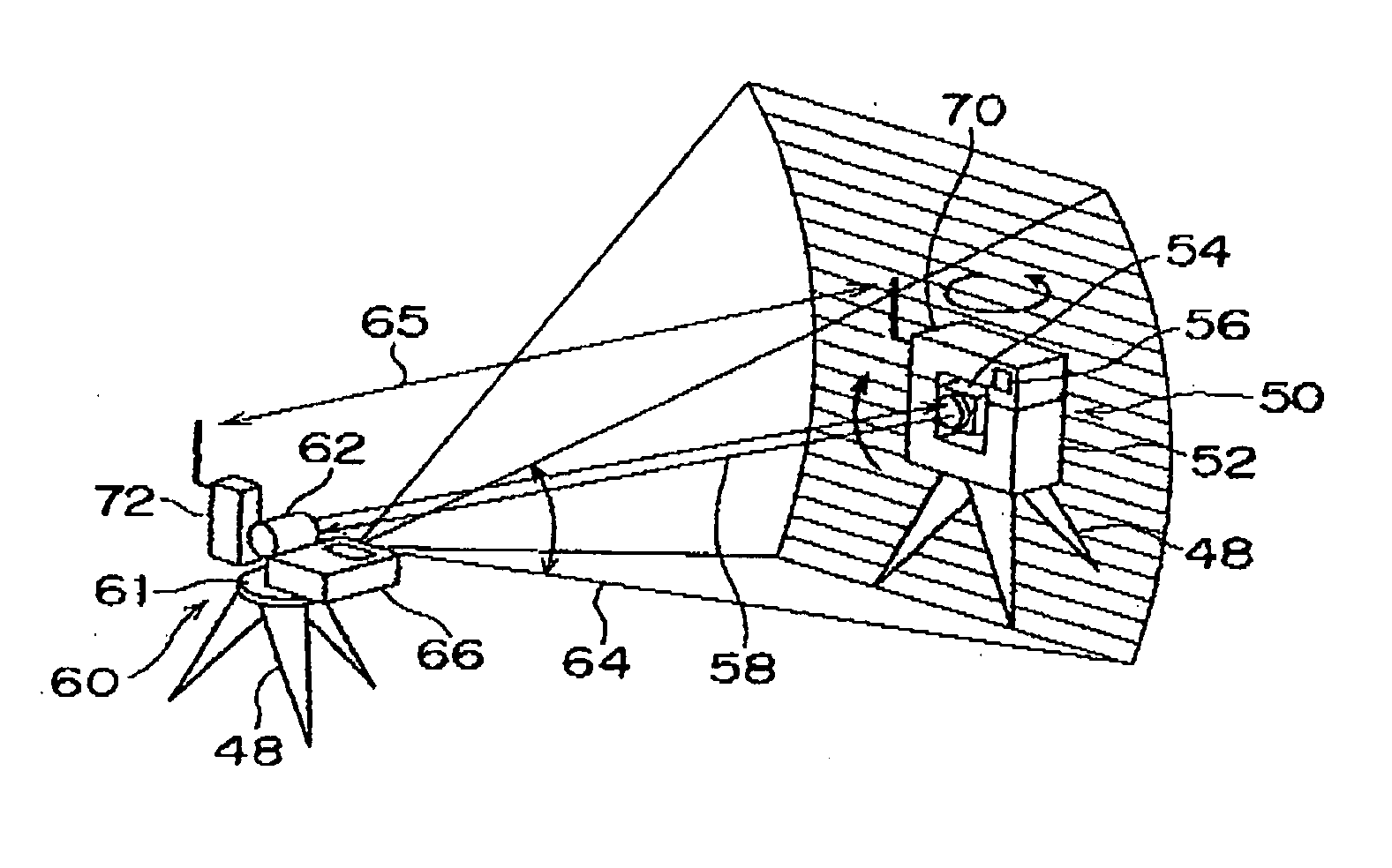
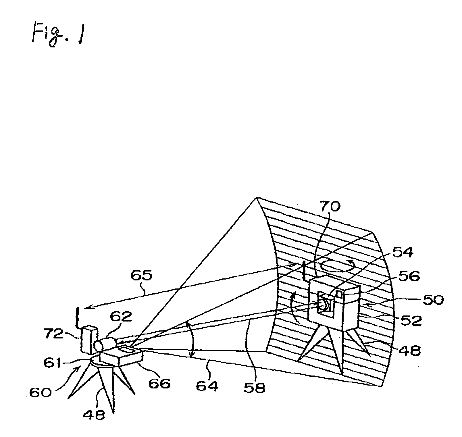
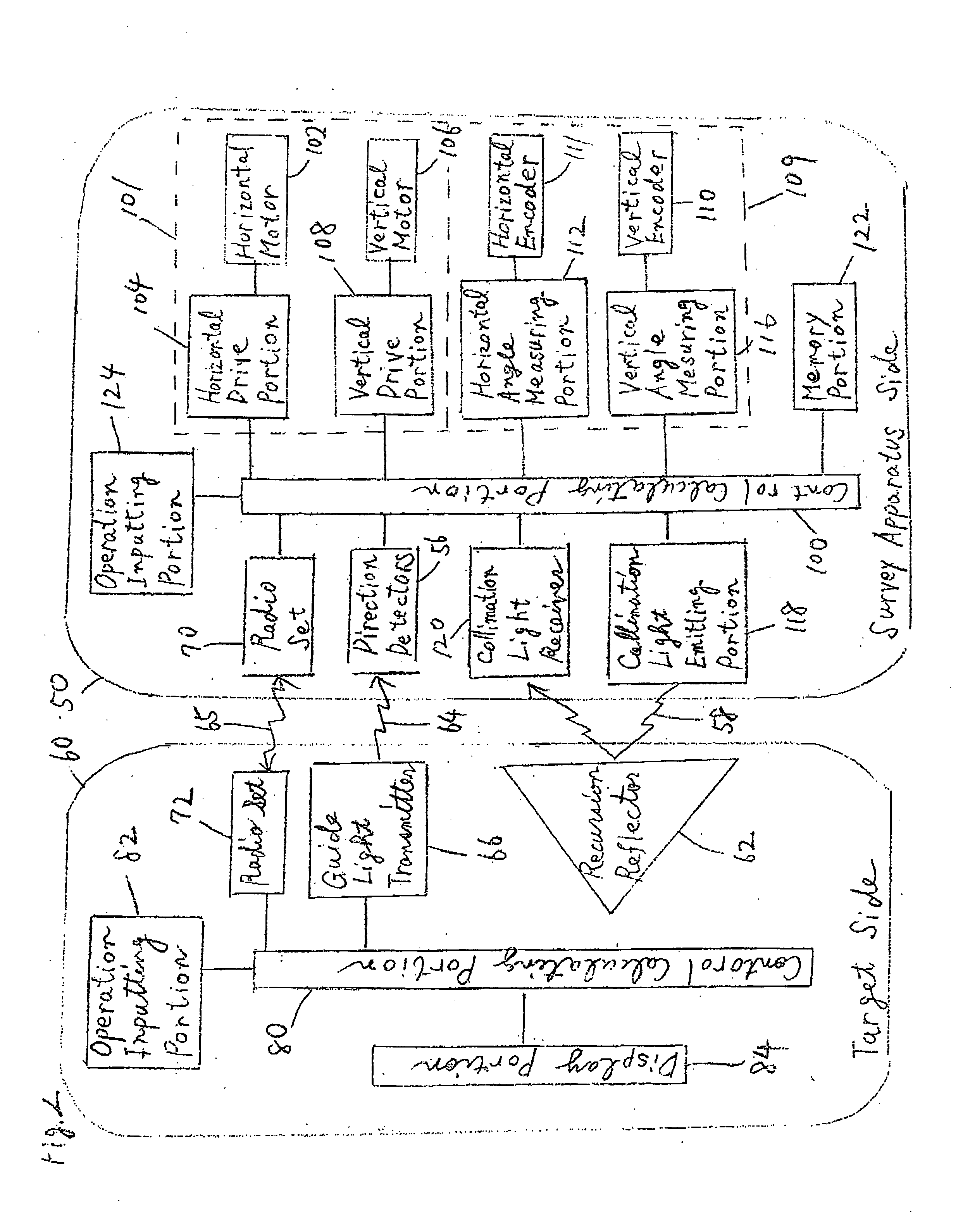
[0021] An embodiment of the present invention will be hereinafter described in accordance with the attached drawings. FIG. 1 is a block diagram of a survey system showing one embodiment of the present invention, and FIG. 2 is a block diagram for explaining an internal structure of a surveying instrument and an internal structure of a target.

[0022] In ...


PUM


Abstract

When light other than guide light is searched by error, the collimation direction of a surveying instrument is changed by emitting a continuous-operation command from the side of a target toward the surveying instrument, and a process for searching proper guide light can be restarted. When a direction detector receives disturbing light differing from guide light in the process of searching the guide light emitted from a guide light transmitter of a target by means of a surveying instrument, a continuous-operation command is emitted from the target toward the surveying instrument. Accordingly, the light receiving direction of the direction detector is changed by driving an instrument body, and a horizontal or vertical rotation is made to a position deviating from a light receiving range obtained when the direction detector receives the disturbing light, and thereafter the process of searching the guide light is restarted.

Description

FIELD OF THE INVENTION [0001] The present invention relates to a survey system capable of remotely controlling a surveying instrument from the side of a target by a single person. BACKGROUND OF THE INVENTION [0002] Conventionally, an operator has been forced by necessity of collimating a target placed on a survey point through manual operations when the position of the survey point or the like is measured by a surveying instrument such as a total station (electronic distance / angle meter). In recent years, a surveying instrument capable of automatically collimating a target by means of an automatic collimator has been proposed in order to lessen the labor of the operator and reduce collimation errors committed by the operator. The surveying instrument provided with the automatic collimator can automatically direct a telescope toward a target by calculating the direction of the target in such a way as to emit collimation light along the optical axis of the telescope of the surveying i...

Claims


Application Information

Patent Timeline
Patent Type & Authority Applications(United States)
IPC IPC(8): G01B11/26G01C1/00G01C15/06G01C15/00
CPCG01C15/002
Inventor CHIBA, MINORU
Owner SOKKOIA COMPANY LIMITED
Learn More