
An interference microscope autofocus device and method

An interference microscope and auto-focus technology, which is applied in the field of interference microscope, can solve the problems of large size, insufficient reliability, and long time consumption, and achieve the effects of reducing the size of the instrument, overcoming the failure of auto-focusing, and reducing costs

Active Publication Date: 2020-11-10
INST OF MACHINERY MFG TECH CHINA ACAD OF ENG PHYSICS
View PDF12 Cites 0 Cited by
  • Summary
  • Abstract
  • Description
  • Claims
  • Application Information

AI Technical Summary

Problems solved by technology

[0005] The purpose of the present invention is to provide an interference microscope autofocus device to solve the problems of time-consuming, large volume and insufficient reliability in the focusing method of the interference microscope in the prior art, and realize the premise of not increasing the volume of the interference microscope instrument Under the condition of fast and reliable autofocus, and the focus process is easy to operate and has a high degree of automation

Method used


Image

  • An interference microscope autofocus device and method
  • An interference microscope autofocus device and method
  • An interference microscope autofocus device and method

Examples


Embodiment Construction

[0043] In order to make the purpose, technical solutions and advantages of the present invention clearer, the present invention will be further described in detail below in conjunction with the examples and accompanying drawings. As a limitation of the present invention.

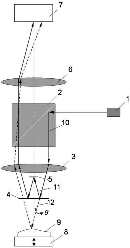
[0044] Such as figure 1 In the shown interference microscope autofocus device, the illumination beamsplitter 2, the microscope objective lens 3, the interference beamsplitter 4, the reference mirror 5, the tube lens 6, and the camera 7 are aligned and arranged at the center, and the center line forms an optical axis. The outgoing light of the unit 1 is perpendicular to the optical axis, and the moving table 8 can move linearly along the optical axis.

[0045] The illumination unit 1 adopts a laser diode with a wavelength of 650nm, and the diameter of the collimated beam emitted is about 2mm. The collimated beam is reflected by the illumination beam splitter 2 to form an illumination beam 10 parallel to the ...


PUM


Abstract

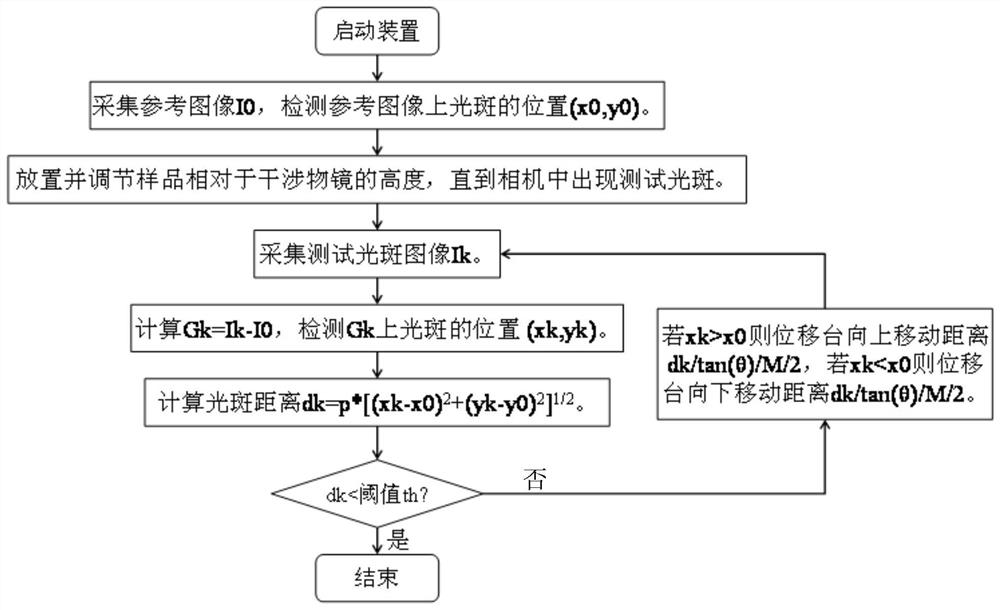
The invention discloses an interference microscope autofocusing device and method. An illumination unit emits a collimated beam. The collimated beam is reflected by an illumination beam splitter to form an illumination beam. After the illumination beam passes through a microscope objective, a part of the beam is reflected by an interference beam splitter to form a reference beam, and the other part is transmitted through the interference beam splitter to form a test beam. The reference beam is sequentially reflected by a reference mirror and the interference beam splitter, and then sequentially transmitted through the microscope objective, the illumination beam splitter and a tube mirror to form a reference spot on a camera. The test beam irradiates a sample, is reflected, and is sequentially transmitted through the interference beam splitter, the microscope objective, the illumination beam splitter and the tube mirror to form a test spot on the camera. According to the invention, the problems of long time, large volume and insufficient reliability of the focusing method of an interference microscope in the prior art are solved; without increasing the volume of the interference microscope, quick and reliable autofocusing is realized; and the focusing process has the advantages of easy operation and high degree of automation.

Description

technical field [0001] The invention relates to the field of interference microscopes, in particular to an interference microscope autofocus device and method. Background technique [0002] Interference microscopy is an important tool for surface topography and film detection, widely used in machinery, electronics, optics, materials and other fields. The interference microscope integrates the functions of microscope and interferometry, and uses a microscope objective to magnify the surface of the sample to obtain the fine structure of the surface. The interference microscope is precisely adjusted so that the reference mirror is located on the object surface of the microscope objective lens, which ensures clear imaging and high-contrast interference fringes. Interference microscopes need to work in a quasi-focus state. Quasi-focus means clear imaging and interference fringes appear, otherwise it is called "out of focus". Therefore, finding a clear imaging position and inter...

Claims


Application Information

Patent Timeline
Patent Type & Authority Patents(China)
IPC IPC(8): G01B9/04G01B9/02G02B21/24G02B21/36
CPCG01B9/02001G01B9/02015G01B9/0203G01B9/02096G01B9/04G02B21/241G02B21/361
Inventor 刘乾李璐璐张辉黄小津
Owner INST OF MACHINERY MFG TECH CHINA ACAD OF ENG PHYSICS
Learn More