Alignment method

A technology for aligning marks and predetermined lines, which is applied in the direction of instruments, laser welding equipment, electrical components, etc., can solve the problems of time-consuming and other problems, and achieve the effect of reliable search and shortened alignment time

Pending Publication Date: 2020-02-11
DISCO CORP
View PDF5 Cites 0 Cited by
  • Summary
  • Abstract
  • Description
  • Claims
  • Application Information

AI Technical Summary

Problems solved by technology

Therefore, the imaging unit is moved to a position adjacent to the previous imaging position by the distance obtained by subtracting the size of the target image from the size of the entire image. Therefore, when the target image is large, the amount of movement of the imaging area is reduced. Therefore, it is necessary to Moving the shooting position multiple times in a spiral creates the problem of taking time to find macro alignment marks

Method used


Image

  • Alignment method
  • Alignment method
  • Alignment method

Examples


Embodiment Construction

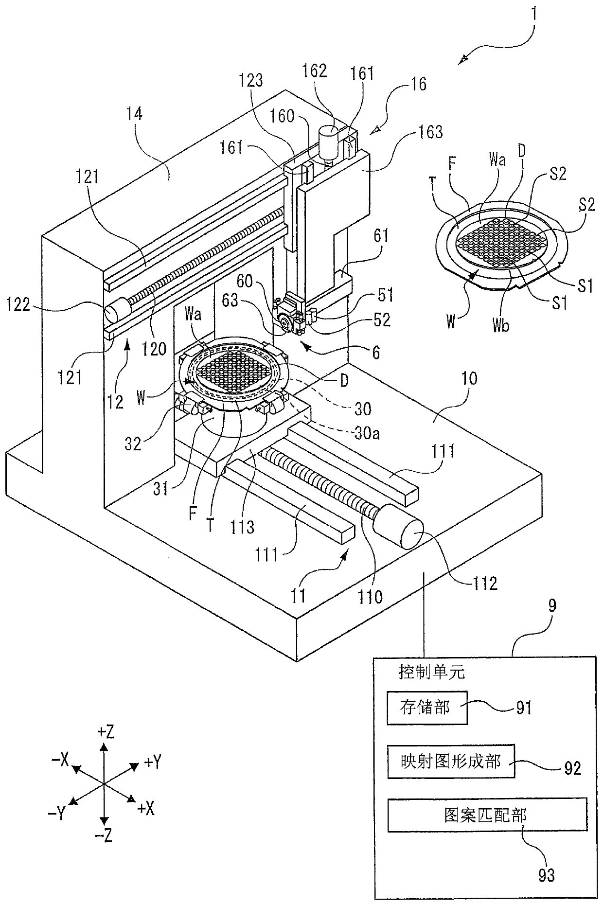
[0027] figure 1 The illustrated cutting device 1 is a device that rotates a cutting tool 63 included in the cutting unit 6 and cuts the wafer W into a plate-shaped workpiece held by the chuck table 30 to perform cutting processing.

[0028] The base 10 of the cutting device 1 is provided with a cutting feed unit 11 that reciprocates the chuck table 30 in the cutting feed direction (X-axis direction). The cutting and feeding unit 11 includes: a ball screw 110 having an axis in the X-axis direction; a pair of guide rails 111 arranged in parallel with the ball screw 110; a motor 112 that rotates the ball screw 110; and The movable plate 113 has an inner nut screwed with the ball screw 110, and the bottom of the movable plate 113 is in sliding contact with the guide rail 111. When the motor 112 rotates the ball screw 110, the movable plate 113 is guided by the guide rail 111 to move in the X-axis direction, and the chuck table 30 arranged on the movable plate 113 moves in the X-axis ...


PUM


Abstract

The invention provides an alignment method, which can quickly find an alignment mark. The method includes: 1) registering the alignment mark (MA) in a zone smaller than a shooting area of a camera unit (51); 2) combining a plurality of shot images to obtain a combined image (G1) which contains the alignment mark, and forming a mapping figure (K) that stores the directional distance of the alignment mark from the pixels of the combined image; 3) performing a first storage step of storing a new shot image (G2) by shooting a new wafer held by a working platform (30); 4) performing a second storage step of searching a brightness distribution area being same as the new shot image from the mapping figure and storing the same brightness distribution area and the directional distances of the alignment mark; 5) determining that whether the alignment mark exists in the shot image (G3) or not, if the alignment mark exists, determining a segment predetermined line according to the alignment mark.

Description

Technical field [0001] The present invention relates to an alignment method for determining a predetermined dividing line of a wafer. Background technique [0002] When a wafer with devices formed in the area divided by the planned dividing line is subjected to cutting processing in which a cutting tool is cut along the planned dividing line to form cutting grooves, or laser processing in which laser beams are irradiated along the planned dividing line to form processing grooves At this time, the device needs to recognize the predetermined dividing line. [0003] The same circuit pattern is formed on the device front surface of the wafer. And, one pattern having a characteristic shape among the circuit patterns is set as a macro alignment mark. In addition, a micro-alignment mark smaller than the macro-alignment mark is set at a predetermined distance from the macro-alignment mark in a predetermined direction. In addition, the planned dividing line is set at a predetermined dist...

Claims


Application Information

Patent Timeline
Patent Type & Authority Applications(China)
IPC IPC(8): H01L21/68H01L21/304G06K9/00G06K9/32
CPCH01L21/681H01L21/3043G06V20/10G06V10/25H01L21/68H01L21/76H01L21/78H01L21/67259H01L21/67092B23K26/38
Inventor 宫田谕
Owner DISCO CORP
Why Eureka
Try Eureka