Jig and carrier plate used for attaching circuit board strength reinforcing pieces

A technology for reinforcing patches and circuit boards, used in printed circuits, printed circuit manufacturing, electrical components, etc. Bit time, improved pasting accuracy, and the effect of improving pasting accuracy

Active Publication Date: 2014-07-30
SHANGHAI MEADVILLE ELECTRONICS
View PDF9 Cites 12 Cited by
  • Summary
  • Abstract
  • Description
  • Claims
  • Application Information

AI Technical Summary

Problems solved by technology

This pasting method is not only low in efficiency and time-consuming, but also poor in fitting accuracy.
When the size of the reinforcement sheet to be pasted is small, it is not only difficult to pick it up by hand, but also cannot be pasted to the designated position precisely by naked eyes
Even if the reinforcing sheet is accurately pasted to the specified position on the circuit board by manual operation, since the reinforcing sheet is bonded to the circuit board through an adhesive, before the adhesive is fully cured, accidentally touching the reinforcing sheet will cause damage. It will cause it to shift and reduce the paste accuracy

Method used


Image

  • Jig and carrier plate used for attaching circuit board strength reinforcing pieces
  • Jig and carrier plate used for attaching circuit board strength reinforcing pieces
  • Jig and carrier plate used for attaching circuit board strength reinforcing pieces

Examples


Embodiment 1

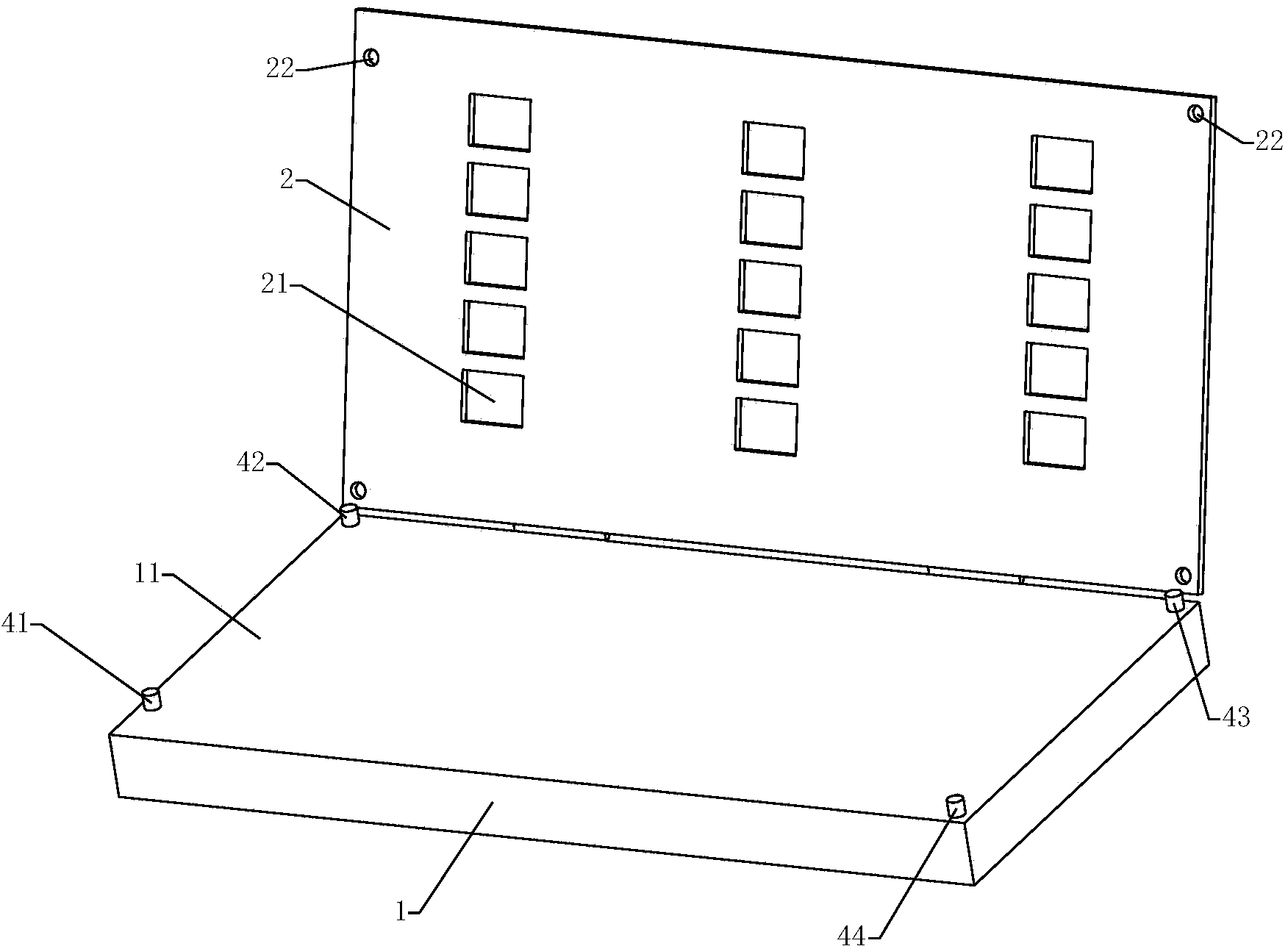
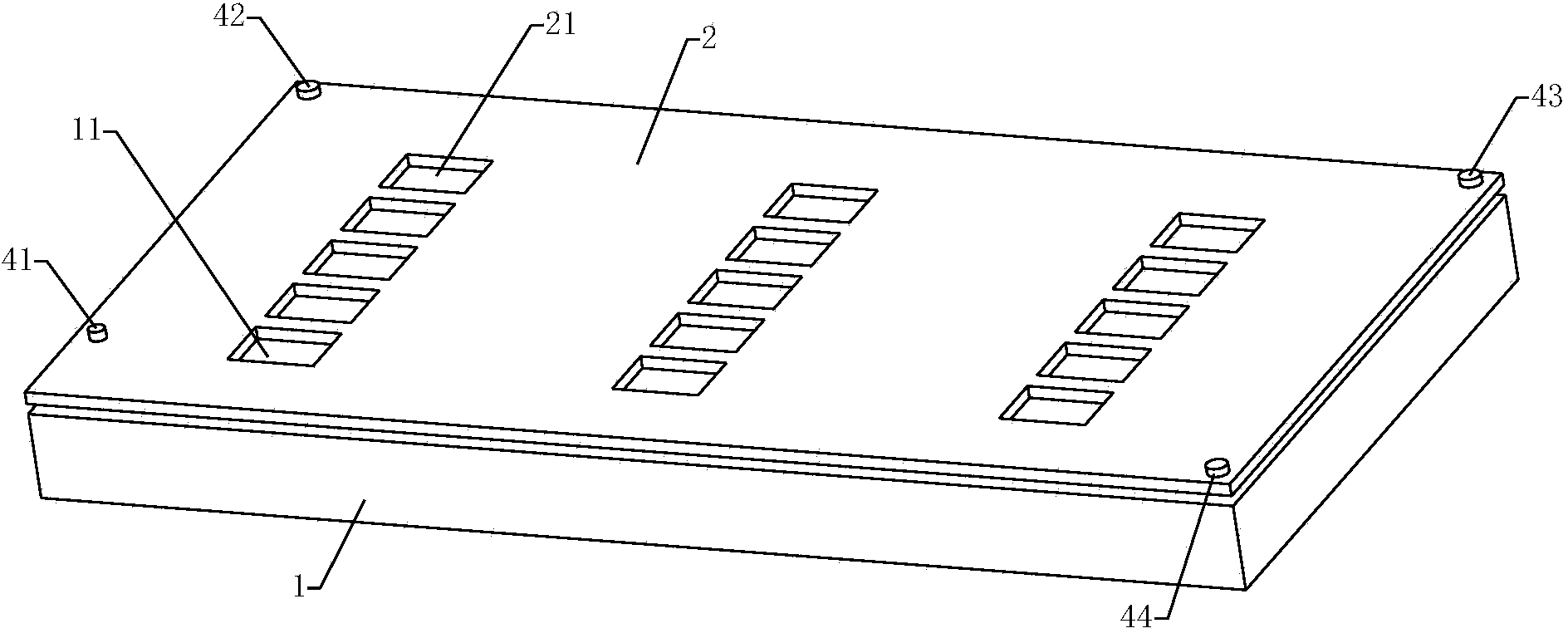
[0044] Such as Figure 1-2As shown, the jig for attaching the circuit board reinforcement patch includes a base plate 1 and a cover plate 2 . The bottom plate 1 has an upper surface 11 for supporting a circuit board. The cover plate 2 is rotatably connected to the bottom plate 1 through a hinge (not shown in the figure). The cover plate 2 is provided with a plurality of first through holes 21 . The shape and size of each first through hole 21 is determined according to each area to be reinforced on the circuit board, so that each first through hole 21 and its corresponding area to be reinforced maintain the same shape and size. In this embodiment, the shapes and sizes of the regions to be reinforced on the circuit board to be reinforced are the same, so the shapes and sizes of the first through holes 21 on the cover plate 2 are the same.

[0045] The jig for attaching the circuit board reinforcement patch also includes a positioning device. The positioning device includes ...

Embodiment 2

[0056] Such as Figure 8 As shown, the jig for attaching circuit board reinforcement patches includes a base plate 1 and a cover plate 2 . The bottom plate 1 has an upper surface 11 for supporting a circuit board. The cover plate 2 is rotatably connected to the bottom plate 1 through a hinge. The cover plate 2 is provided with a plurality of first through holes 21 . The shape and size of each first through hole 21 is determined according to each area to be reinforced on the circuit board, so that each first through hole 21 and its corresponding area to be reinforced maintain the same shape and size. In this embodiment, the shapes and sizes of the regions to be reinforced on the circuit board to be reinforced are the same, so the shapes and sizes of the first through holes 21 on the cover plate 2 are the same.

[0057] The jig for attaching the circuit board reinforcement patch also includes a positioning device. The positioning device includes four cylindrical positioning ...

Embodiment 3

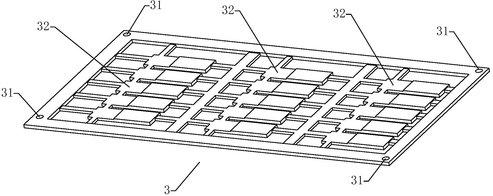
[0073] Such as Figure 9-11 Shown is a reinforcement patch. The reinforcement sheet includes a carrier plate 6 and a plurality of reinforcement sheets 5 . The reinforcement sheet 5 is bonded to the carrier plate 6 by a low-viscosity adhesive.

[0074] The carrier board 6 includes a positioning board 61 and three bonding boards 62 . The positioning plate 61 is provided with a plurality of second through holes 611 , and the shape of the second through holes 611 is the same as that of the reinforcing sheet 5 . The bonding plate 62 is bonded on the positioning plate 61 and covers the second through hole 611 . The reinforcing sheet 5 is inserted into the second through hole 611 and bonded to the bonding plate 62 by a low-viscosity adhesive. The surface of the reinforcement sheet 5 in contact with the adhesive plate 62 is the first surface, and the surface of the reinforcement sheet 5 opposite to the first surface is the second surface, and the second surface is provided with a ...


PUM


Abstract

The invention discloses a jig and carrier plate used for attaching circuit board strength reinforcing pieces. The jig used for attaching the circuit board strength reinforcing pieces is characterized by comprising a bottom plate and a cover plate. The bottom plate is provided with an upper surface used for supporting a circuit board. The cover plate is matched with the bottom plate and used for clamping the circuit board placed on the upper surface. The cover plate is provided with at least one first through hole. The first through holes make the circuit board be exposed partially. According to the jig used for attaching the circuit board strength reinforcing pieces, the bottom plate is adopted for supporting the circuit board, the circuit board is covered by the cover plate, and a region, to be reinforced, of the circuit board is exposed through the first through hole in the cover plate, and then the strength reinforcing pieces are embedded into the first through holes to be attached to the circuit board. Due to the fact that the cover plate has a certain thickness, an operator can accurately embed the strength reinforcing pieces into the first through holes and pasting the strength reinforcing pieces to be region to be reinforced, pasting precision is greatly improved, meanwhile, time for alignment through the naked eyes is shortened, and working efficiency is improved.

Description

technical field [0001] The invention relates to the field of printed circuit board manufacturing, in particular to a jig for attaching a circuit board reinforcing patch and a carrier plate for attaching a circuit board reinforcing patch. Background technique [0002] Flexible printed circuit boards are widely used in the printed circuit industry because of their advantages such as lightness, small size, bendability, and three-dimensional wiring. However, when soldering electronic components on a flexible printed circuit board, the flexible circuit board is easy to bend due to its low mechanical strength, which may lead to soldering defects such as cracking of solder legs of the components. In order to avoid the occurrence of welding defects and improve the reliability of the flexible printed circuit board, it is necessary to paste reinforcing sheets on the parts of the welding components to enhance the mechanical strength of the parts. [0003] At present, most of the pasti...

Claims


Application Information

Patent Timeline
Patent Type & Authority Applications(China)
IPC IPC(8): H05K3/00
Inventor 陶伟良黄伟何海洋魏瑀
Owner SHANGHAI MEADVILLE ELECTRONICS
Why Eureka
Try Eureka