Steel plate splicing device

A technology for splicing devices and steel plates, applied in auxiliary devices, welding equipment, auxiliary welding equipment, etc., can solve problems such as unfavorable pre-alignment of steel plates 7 to be welded, low work efficiency, inconvenient removal, etc., so as to speed up heat dissipation and improve Efficiency, the effect of improving alignment efficiency

Inactive Publication Date: 2018-11-30
重庆大江智防特种装备有限公司
View PDF10 Cites 12 Cited by
  • Summary
  • Abstract
  • Description
  • Claims
  • Application Information

AI Technical Summary

Problems solved by technology

This device has the following disadvantages: 1. Use the compression bolt 10 to position and compress the steel plate to be welded, and each compression bolt 10 needs to be screwed up or unscrewed separately, so as to realize the compression and relaxation of the steel plate 7 to be welded , the work efficiency is low, which is not conducive to production
2. The whole device is fixed on the workbench through the fixing seat 8 and cannot be moved, which is not conducive to the pre-alignment of the steel plate 7 to be welded, and it is also inconvenient to remove from the device after welding, and the operation is time-consuming

Method used


Image

  • Steel plate splicing device
  • Steel plate splicing device
  • Steel plate splicing device

Examples


Embodiment Construction

[0031] The present invention will be described in detail below in conjunction with the accompanying drawings.

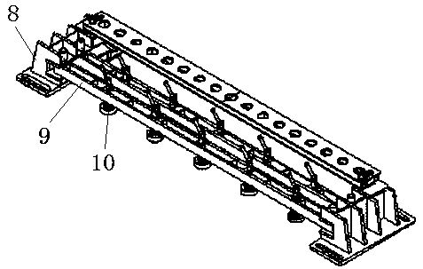
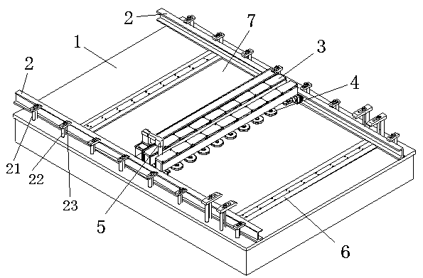
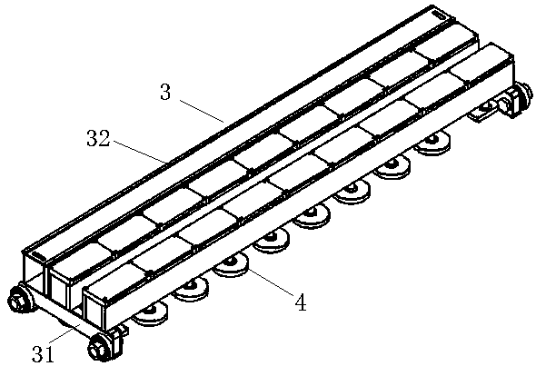
[0032] see figure 2 and image 3 , the steel plate splicing device shown includes a workbench 1, a guide rail 2, a beam 3, a pressing mechanism 4, a welding mechanism 5 and a copper pad 6; the number of the guide rails 2 is two, and they are arranged in parallel on the workbench 1 , the spacing between the guide rails 2 is adjusted according to the size of the steel plate 7 to be welded; the two ends of the beam 3 are provided with sliding seats 31 correspondingly matched with the guide rails 2, and the pressing mechanism 4 is fixed on the beam 1 for The steel plate 7 to be welded is positioned at the welding butt joint, and the upper surface of the beam 1 is provided with a guide rail 32, and the welding mechanism 4 is slidably arranged on the guide rail 32; corresponding to the weld position.

[0033] see Figure 4 A plurality of accommodating cavities are arr...


PUM


Abstract

The invention discloses a steel plate splicing device. The steel plate splicing device comprises a workbench, two guide rails, a crossbeam, a compaction mechanism, a welding mechanism and copper pad bases, wherein the two guide rails are arranged on the workbench in parallel, and the distance between the guide rails can be adjusted according to the sizes of steel plates to be welded; sliding basescorrespondingly matched with the guide rails are arranged at the two ends of the crossbeam; the compaction mechanism is fixed on the crossbeam and used for positioning the steel plates to be welded at the welding butt positions; guide sliding rails are arranged on the upper surface of the crossbeam, and the welding mechanism is arranged on the guide sliding rails in a sliding manner; the copper pad bases are fixed on the workbench and correspond to welded joint positions of the steel plates to be welded. The steel plate splicing device can improve the splicing efficiency of the steel plates and guarantees the quality of welded joints.

Description

technical field [0001] The invention relates to mechanical equipment, in particular to a steel plate splicing device. Background technique [0002] At present, in automobile production, the size of the top and side panels on the body is relatively large. When the panels are manufactured in conventional sizes, the dimensions in the length direction can meet the requirements, and the dimensions in the width direction are insufficient. See figure 1 , two steel plates need to be spliced ​​together. [0003] see figure 2 , the existing steel plate splicing device shown includes two fixed seats 8 fixedly connected to the workbench, an existing crossbeam 9 located between the two fixed seats 8, and two rows of compression joints are screwed on the existing crossbeam 9 The bolt 10, the bolt head of the compression bolt 10 is located below the existing beam 9, and is used to compress the steel plate to be welded. This device has the following disadvantages: 1. Use the compression...

Claims


Application Information

Patent Timeline
Patent Type & Authority Applications(China)
IPC IPC(8): B23K37/02B23K37/04
CPCB23K37/0205B23K37/0408B23K37/0461
Inventor 孔宪国蒋黎明涂永平黄胡林赵强杨中建余长海
Owner 重庆大江智防特种装备有限公司
Why Eureka
Try Eureka