Position control arrangement, especially for a surveying instrument, and a surveying instrument

a position control and surveying instrument technology, applied in the field of surveying instruments, can solve the problems of increasing the cost of surveying instruments, increasing the complexity of surveying instruments, and affecting the accuracy of surveying instruments, so as to improve the position control arrangement, improve the accuracy of use, and improve the effect of the position control arrangemen

Inactive Publication Date: 2010-07-27
TRIMBLE A B A CORP OF SWEDEN
View PDF19 Cites 48 Cited by
  • Summary
  • Abstract
  • Description
  • Claims
  • Application Information

AI Technical Summary

Benefits of technology

[0007]It is an object of the invention to provide an improved position control arrangement that is simpler and that is cheaper to manufacture. It is another object to provide a position control arrangement that is highly accurate in use, while being simple to operate. A further object is to provide an arrangement that requires less space. A still further object is to provide an improved surveying instrument.SUMMARY OF THE INVENTION
[0011]By providing a direct-drive electric motor the need for a gear arrangement is eliminated, and by making it possible to selectively operate the motor in a normal mode or in a friction mode, the need for a conventional friction clutch for allowing a forced rotation of the movable unit is eliminated.
[0012]By providing means for automatically switching the mode of operation for the motor in response to the presence of an external force influencing the movable unit, a simple operation is made possible, since the operator does not have to be concerned about selecting a mode of operation.
[0013]In a further embodiment a friction control unit is adapted to control, in friction mode, the magnitude of resistance to forced rotation. The friction control unit is also arranged to limit such resistance to a selected value. In this way good precision can be obtained when manually shifting the position of the movable unit.
[0014]The elimination of the gear arrangement also provides a more quiet and quick operation when shifting the movable unit from one position to another.

Problems solved by technology

Such an instrument with a suitable gear arrangement is expensive.
By using a gear arrangement and two angle sensors as well as a friction clutch at each axis around which the movable unit is to be moved by a motor, the surveying instrument becomes relatively complicated and expensive.

Method used


Image

  • Position control arrangement, especially for a surveying instrument, and a surveying instrument
  • Position control arrangement, especially for a surveying instrument, and a surveying instrument
  • Position control arrangement, especially for a surveying instrument, and a surveying instrument

Examples


Embodiment Construction

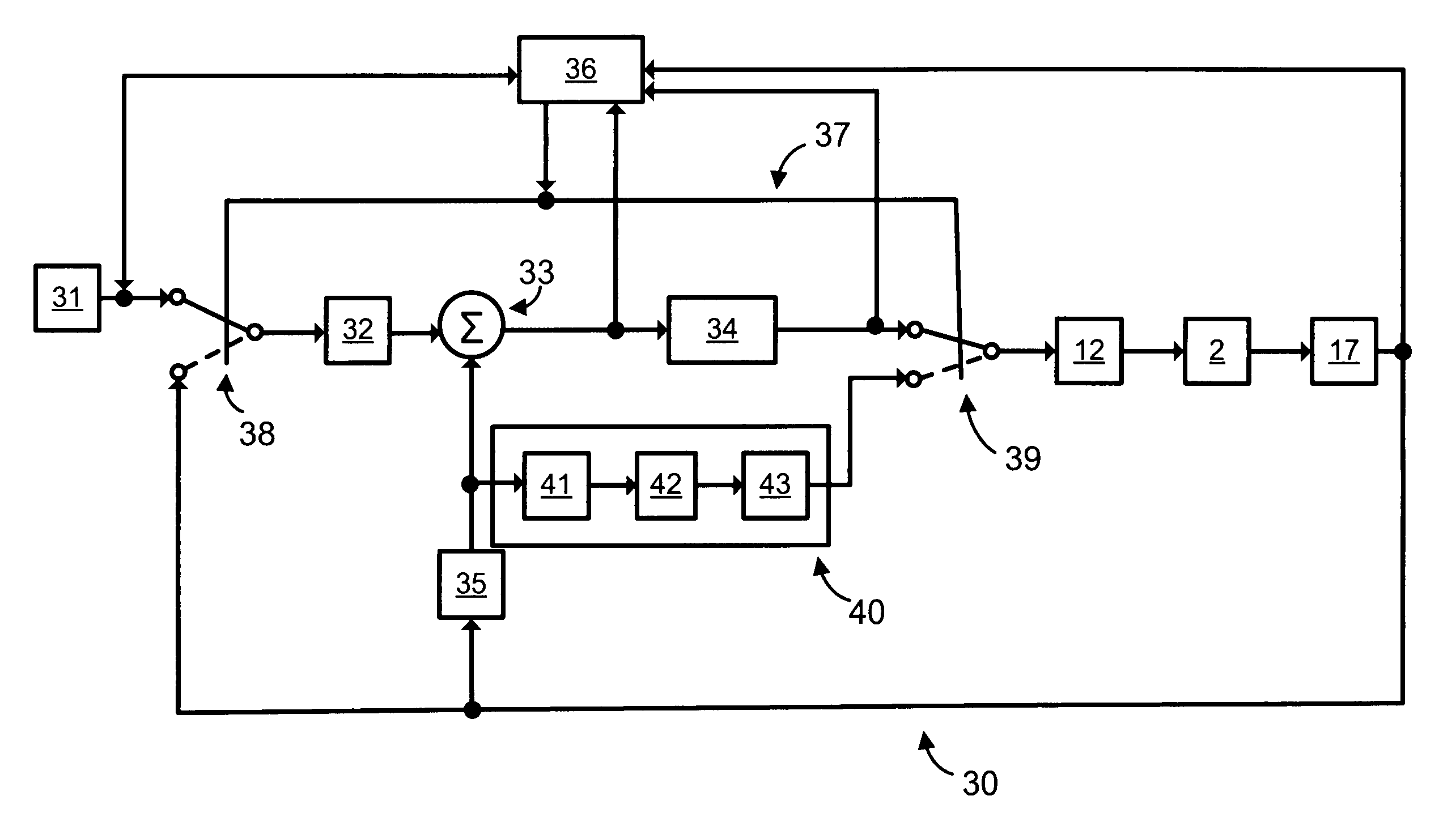
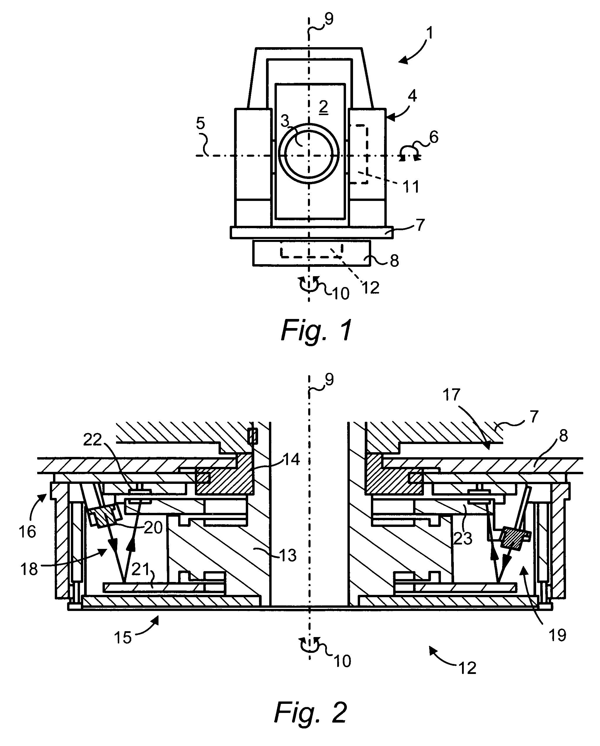
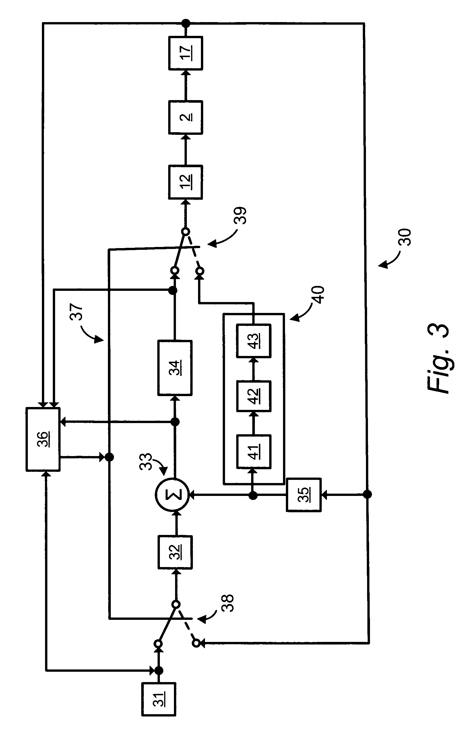
[0022]FIG. 1 illustrates one application for the control system of an embodiment of the present invention. In FIG. 1 there is illustrated a front view of a surveying instrument 1 of the type commonly referred to as a total station. A movable unit 2, comprising optical equipment of the total station, as represented by a lens 3, is supported in a housing 4 in such a manner that it may be pivoted relative to the housing 4 around an essentially horizontal axis 5, as indicated by double arrow 6. The housing 4 comprises a base 7 by means of which it is supported on a stand 8 in such a manner that it is rotatable relative to the stand 8 around an essentially vertical axis 9, as indicated by double arrow 10. Thus, by rotating the movable unit 2 around the two axes 5 and 9 the movable unit 2 can be oriented in any desired position for the purpose of carrying out an intended surveying operation. For movement of the movable unit 2 around the axis 5 there is provided a motor arrangement 11 in t...


PUM


Abstract

In a position control arrangement for controlling the rotational position of a movable unit, especially for a surveying instrument, an electric motor is arranged to rotate the movable unit around an axis of rotation, and there are controllers for enabling the motor to stop the movable unit in a desired rotational position. The motor is a direct drive motor, the shaft of which forms the axis of rotation for the movable unit, and the motor is arranged to selectively operate in either a first, normal mode for rotating the movable unit to a desired position, or in a second, friction mode for providing resistance to a forced rotation of the movable unit from a predetermined position to a new position. A control unit detects the presence of a forced rotation and automatically changes the mode of operation in response thereto.

Description

[0001]This application is a divisional of U.S. application Ser. No. 11 / 084,797, now U.S. Pat. No. 7,634,381, filed Mar. 18, 2005, which is a continuation-in-part (CIP) of International Application No. PCT / SE2003 / 001375, filed Sep. 4, 2003, claiming priority of Swedish Application No. SE 0202793-6, filed Sep. 20, 2002, the entire contents of each of these applications are incorporated herein by reference.FIELD OF THE INVENTION[0002]The present invention relates to a position control arrangement, and in particular to a position control arrangement for controlling the operation of a motor adapted to rotate a movable unit, which may be an optical movable unit of the type forming part of a surveying instrument, including a survey instrument known as a total station.BACKGROUND OF THE INVENTION[0003]In surveying instruments, especially in so-called total stations, it is often required to position a movable unit in the instrument by rotating the movable unit around a horizontal or a vertica...

Claims


Application Information

Patent Timeline
Patent Type & Authority Patents(United States)
IPC IPC(8): G01C17/00G01C19/00G01C15/00G05B19/19G06F15/00
CPCG01C15/002G05B19/19G05B2219/42091G05B2219/42104G01C1/00G01C15/00G05B7/02G06F15/00
Inventor WESTERMARK, MAGNUSHERTZMAN, MIKAELBERG, ULFKLANG, THOMAS
Owner TRIMBLE A B A CORP OF SWEDEN
Why Eureka
Try Eureka