Eureka AIR delivers breakthrough ideas for toughest innovation challenges, trusted by R&D personnel around the world.

Droplet discharge head and inkjet recording apparatus

a technology of inkjet recording apparatus and droplet discharge head, which is applied in the direction of printing, inking apparatus, other printing apparatus, etc., can solve the problems of increased ink consumption for carrying out suction action, increased pressure to circulation channel, and increased power of discharge actuator, so as to facilitate manufacturing and reduce costs

Inactive Publication Date: 2006-10-31
FUJIFILM CORP
View PDF19 Cites 29 Cited by
  • Summary
  • Abstract
  • Description
  • Claims
  • Application Information

AI Technical Summary

Benefits of technology

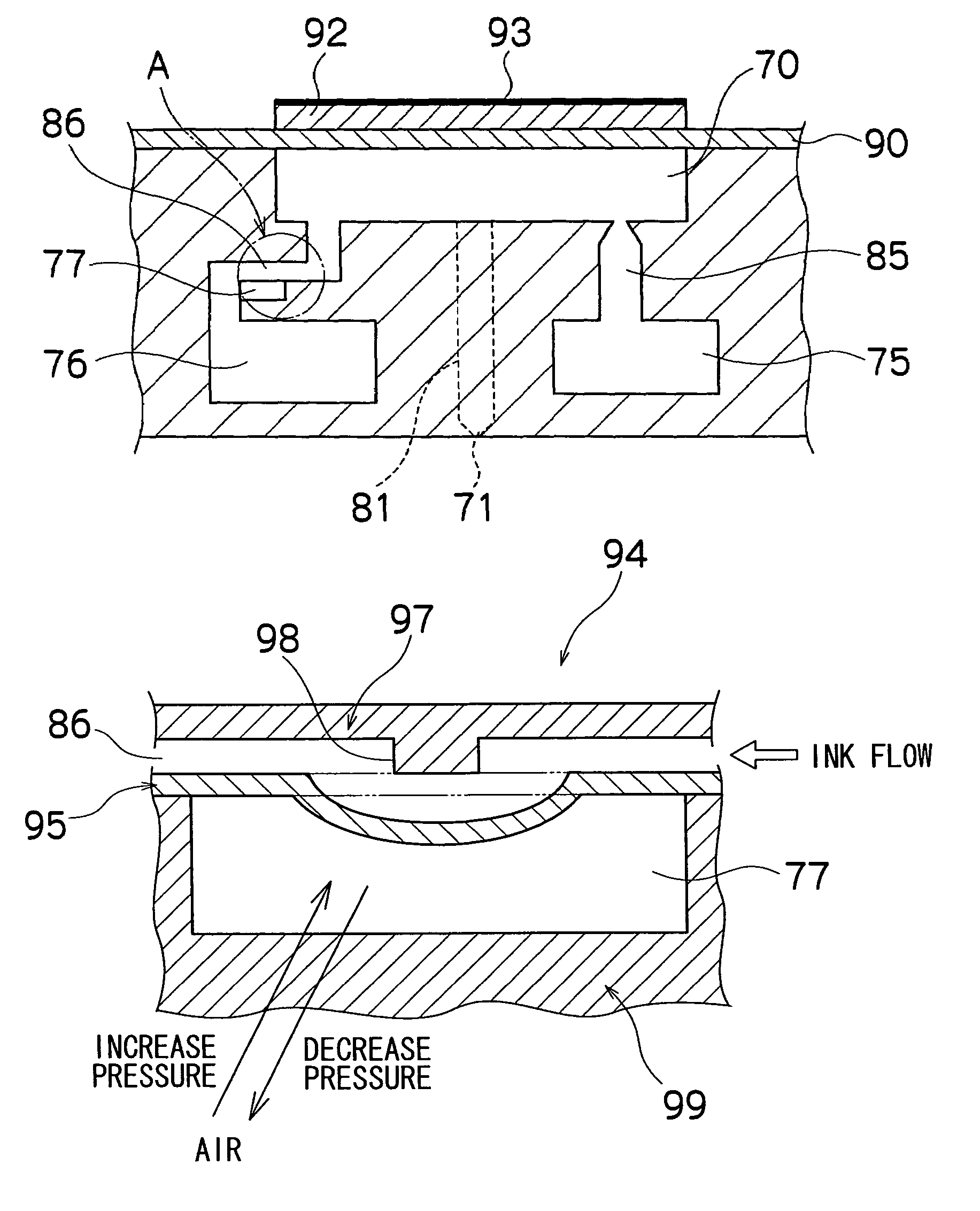
[0013]According to the present invention, the planar shape of the pressure chamber is given a substantially triangular shape, and liquid channel ports in communication with each of the first, second, and third conduits, which are the inflow and outflow channels of the pressure chamber, are respectively provided to positions corresponding to the vertices, so that the flow of liquid inside the pressure chamber does not easily pool, and the accumulation of bubbles in the pressure chamber can be prevented. Also, the liquid that was caused to flow from the second conduit into the pressure chamber can be drawn out from the pressure chamber through the third conduit, so that bubbles inside the pressure chamber can be removed. Furthermore, by closing the switching device during discharge operation for discharging droplets from the nozzle, pressure loss can be prevented and discharge force can be assured. A plurality of pressure chambers can be arranged in a two-dimensional, high-density configuration with a structure in which the planar shape of the pressure chamber is a substantially triangular shape, and higher nozzle density can be realized.
[0016]Preferably, the droplet discharge head further comprises a switching control device which simultaneously controlling a plurality of the switching devices disposed correspondingly to the plurality of the pressure chambers. In comparison with a configuration in which a plurality of switching devices is individually disposed correspondingly to the plurality of pressure chambers, this aspect allows the number of actuators and other components for opening and closing to be reduced, costs to be cut, manufacturing to be facilitated.

Problems solved by technology

However, this action has a drawback in that ink consumption for carrying out the suctioning action is increased.
However, the configurations proposed in Japanese Patent Application Publication Nos. 6-24000 and 2002-254643 result in the release of pressure to the circulation channel during discharge driving, so a greater amount of discharge actuator power is required.
The configuration proposed in Japanese Patent Application Publication No. 2002-355961 allows bubbles inside the common flow channel to be removed, but bubbles inside the pressure chamber cannot be removed.

Method used


Image

  • Droplet discharge head and inkjet recording apparatus
  • Droplet discharge head and inkjet recording apparatus
  • Droplet discharge head and inkjet recording apparatus

Examples


Embodiment Construction

General Configuration of an Inkjet Recording Apparatus

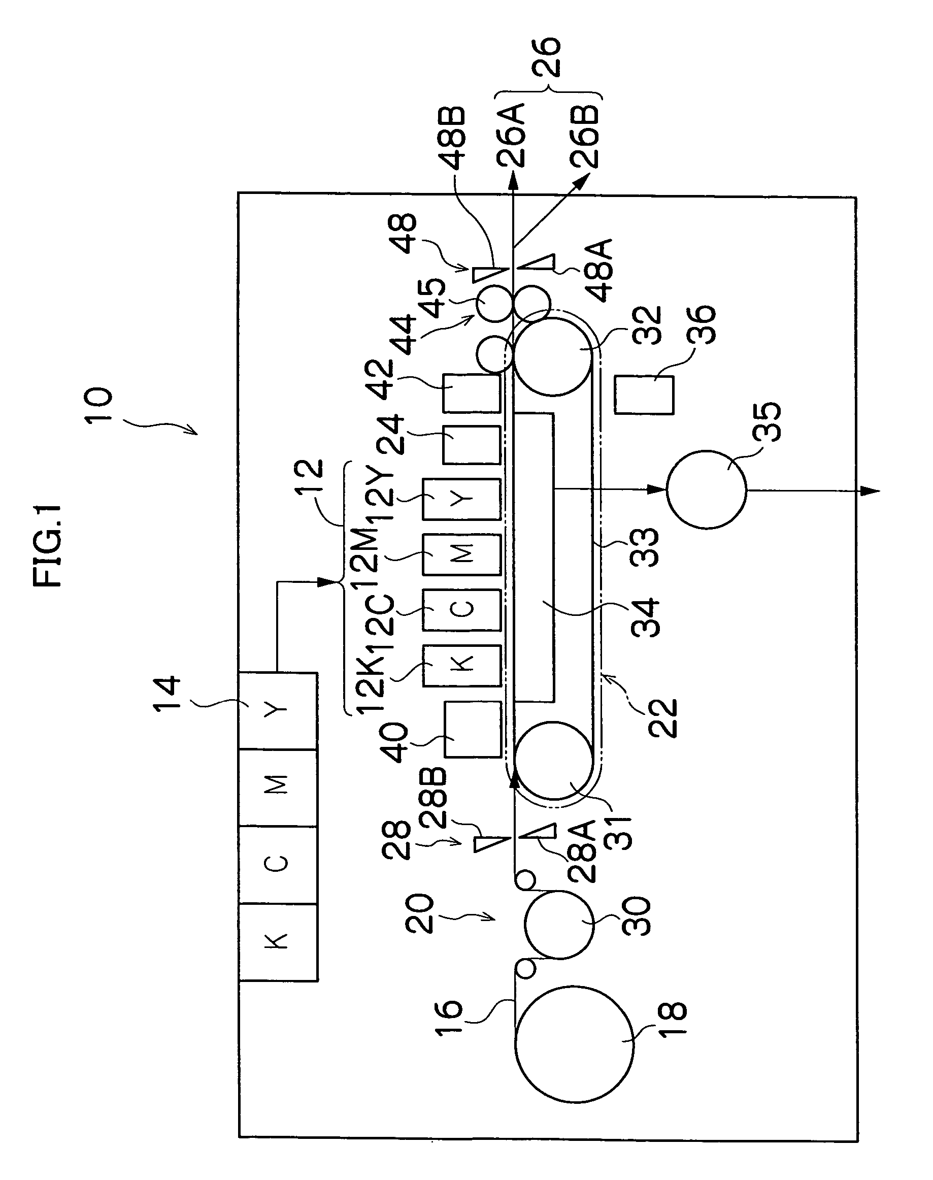
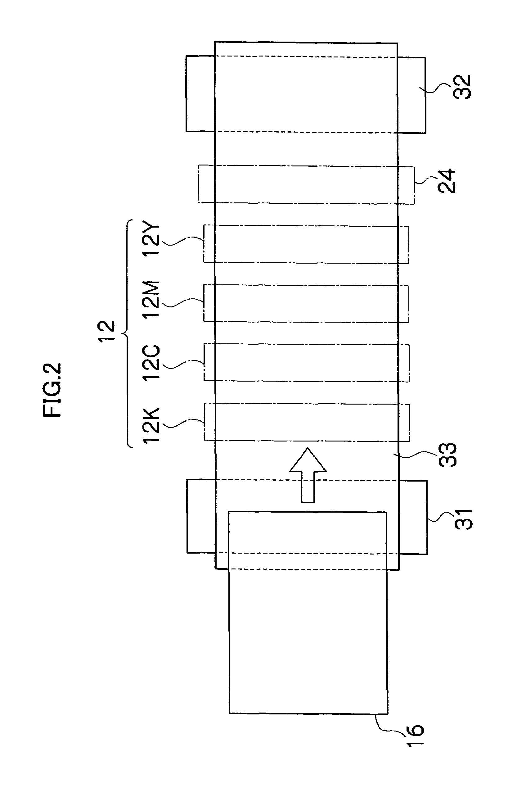
[0047]FIG. 1 is a general schematic drawing of an inkjet recording apparatus according to an embodiment of the present invention. As shown in FIG. 1, the inkjet recording apparatus 10 comprises: a printing unit 12 having a plurality of print heads 12K, 12C, 12M, and 12Y for ink colors of black (K), cyan (C), magenta (M), and yellow (Y), respectively; an ink storing / loading unit 14 for storing inks to be supplied to the print heads 12K, 12C, 12M, and 12Y; a paper supply unit 18 for supplying recording paper 16; a decurling unit 20 for removing curl in the recording paper 16; a suction belt conveyance unit 22 disposed facing the nozzle face (ink-droplet ejection face) of the print unit 12, for conveying the recording paper 16 while keeping the recording paper 16 flat; a print determination unit 24 for reading the printed result produced by the printing unit 12; and a paper output unit 26 for outputting image-printed recording paper...


PUM


Abstract

The droplet discharge head comprises: a nozzle which discharges droplets of a liquid; a pressure chamber which is in communication with the nozzle and is filled with the liquid to be discharged from the nozzle; and a pressure generation device which generates pressure variation in the liquid inside the pressure chamber and causes the droplets to be discharged from the nozzle, wherein: the pressure chamber has a substantially triangular planar shape; the pressure chamber is provided with a first conduit which conducts the liquid from the pressure chamber to the nozzle, a second conduit which causes the liquid to flow into the pressure chamber, a third conduit which drains the liquid in the pressure chamber to exterior of the pressure chamber, and a switching device which opens and closes a flow channel in at least one of the second and third conduits; and the first, second and third conduits are connected to the pressure chamber at positions in vicinity of different vertices of the substantially triangular shape, respectively.

Description

[0001]This Nonprovisional application claims priority under 35 U.S.C. § 119(a) on Patent Application No(s). 2003-332466 filed in Japan on Sep. 24, 2003, the entire contents of which are hereby incorporated by reference.BACKGROUND OF THE INVENTION[0002]1. Field of the Invention[0003]The present invention relates to a droplet discharge head and inkjet recording apparatus, and more specifically to the structure for a droplet discharge head effective for removing bubbles within a pressure chamber in communication with a nozzle (droplet discharge port), and to an inkjet recording apparatus that uses the head.[0004]2. Description of the Related Art[0005]Inkjet recording apparatuses deposit ink droplets on a recording medium by relatively moving recording paper or another recording medium with respect to a recording head provided with ink discharge nozzles while discharging ink from the recording head in accordance with a print signal, and an image is formed on the printing medium by the i...

Claims


Application Information

Patent Timeline
Patent Type & Authority Patents(United States)
IPC IPC(8): B41J2/045B41J2/14B41J2/19
CPCB41J2/14233B41J2/19B41J11/0005B41J2002/14306B41J2002/14459B41J2202/12
Inventor KODAMA, KENICHI
Owner FUJIFILM CORP
Why Eureka
Eureka Blog
Learn More