
Ribbon cassette with ink ribbon slack prevention mechanism

a technology of ink ribbon and slack, which is applied in the direction of ink ribbon, printing, inking apparatus, etc., can solve the problems of ribbon taking up spool to rotate, preventing correct printing, and preventing the inclusion of ink ribbon

Active Publication Date: 2006-10-31
BROTHER KOGYO KK
View PDF19 Cites 105 Cited by
  • Summary
  • Abstract
  • Description
  • Claims
  • Application Information

AI Technical Summary

Benefits of technology

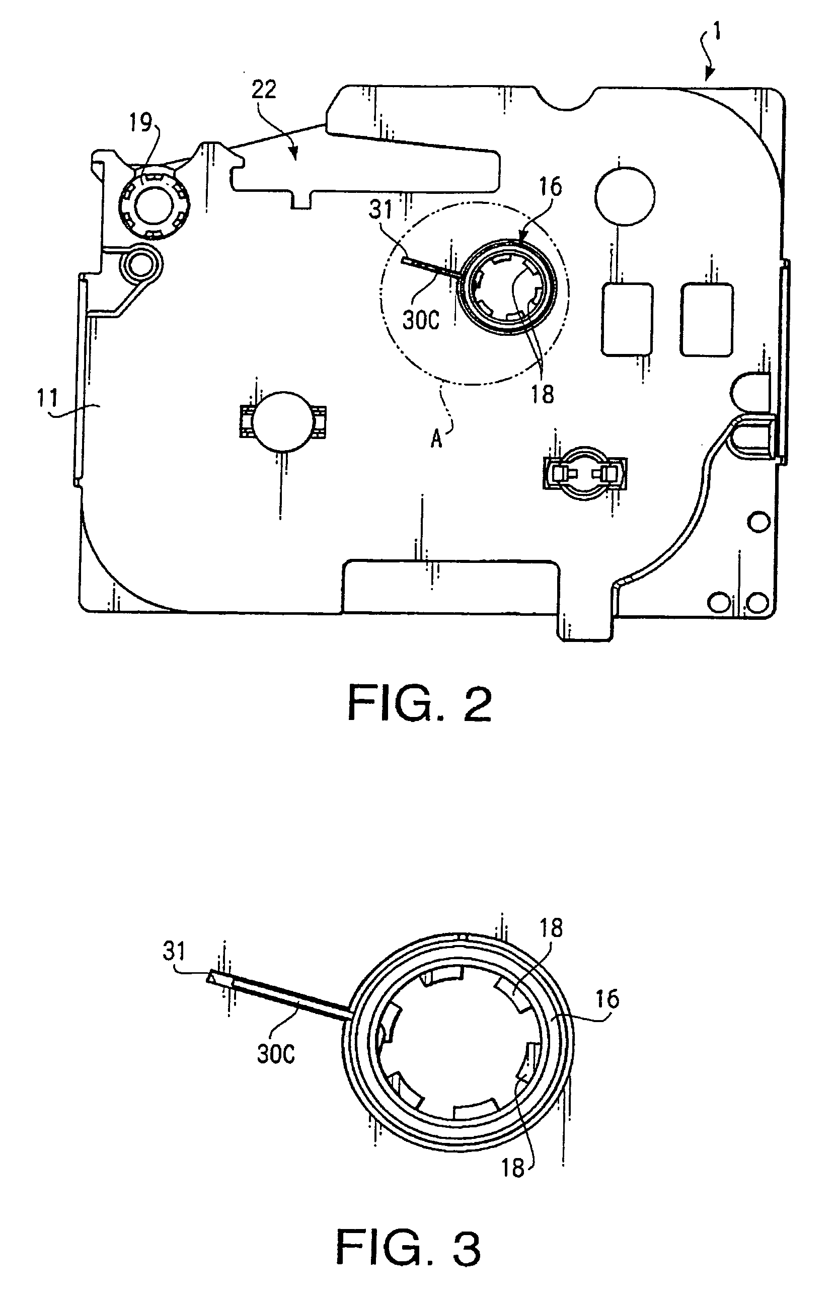
[0009]A ribbon cassette according to an aspect of the invention includes a ribbon supply spool, and a ribbon take up spool that takes up an ink ribbon from the ribbon supply spool by rotating in a first rotation direction. The ribbon take up spool is provided with an engaging portion. The ribbon cassette further includes an engaging member that resiliently engages with the engaging portion. By engaging with the engaging portion, the engaging member prevents the ribbon take up spool from rotating in a second rotation direction opposite to the first rotation direction, and hence prevents slack in the ink ribbon from occurring. The engaging member, however, comes off from the engaging portion when the ribbon take up spool rotates in the first direction. Accordingly, the ribbon take up spool can smoothly take up the ink ribbon from the ribbon supply spool.
[0012]In some cases, the ribbon take up spool may be provided with a pair of brims and the ink ribbon may be wound around the ribbon take up spool at a space defined between the pair of brims. In such cases, the engaging portion may be located outside the pair of brims. In a ribbon cassette configured as above, one of the brims is located between the ink ribbon wound around the ribbon take up spool and the engaging portion and prevents the engaging member engaged with the engaging portion from interfering with the ink ribbon.
[0013]Optionally, a cassette case of the ribbon cassette, which accommodates the ribbon supply spool and the ribbon take up spool, may hold the engaging member to prevent it from rotating together with the ribbon take up spool. In this case, the engaging member can reliably prevent the ribbon take up spool from rotating in the second rotation direction.
[0016]Optionally, the engaging member may further include an additional linear portion formed between the bent portion and the arc portion, which is bent inwardly against the arc portion. Such a linear portion biases the engaging member toward the circumferential wall of the ribbon take up spool and thereby ensures the engaging member to engage with the engaging portion.
[0020]In the case the ribbon take up spool is provided with the pair of brims, the circumferential groove and the arc portion may be located outside the pair of brims. In this case, the engaging member may further include an extending portion extending from an end of the arc portion opposite from the linear portion substantially along the radial direction of the ribbon take up spool. Such an extending portion prevents the engaging member from interfering with a burr formed on the brim and precluding smooth rotation of the ribbon take up spool.

Problems solved by technology

When the ribbon cassette is set into a printing device, the slack in the ink ribbon precludes suitable feeding of the ink ribbon from the ribbon cassette and hinders correct printing.
Such a rotation of the driving shaft causes the ribbon take up spool to rotate and generate slack in the ink ribbon.
If the ribbon cassette is set into the printing device without removing the slack in the ink ribbon, the ink ribbon may be jammed within the ribbon cassette and make the ribbon cassette unusable.
However, this is a burdensome procedure for a user and the user may often forget it.
Even if the user has not forgotten to remove the slack in the ink ribbon, the user may rotate the ribbon take up spool in a direction opposite to that for taking up the ink ribbon, resulting in generating more slack in the ribbon.

Method used


Image

  • Ribbon cassette with ink ribbon slack prevention mechanism
  • Ribbon cassette with ink ribbon slack prevention mechanism
  • Ribbon cassette with ink ribbon slack prevention mechanism

Examples


Embodiment Construction

[0033]Hereinafter, an embodiment of the invention will be described with reference to the accompanying drawings.

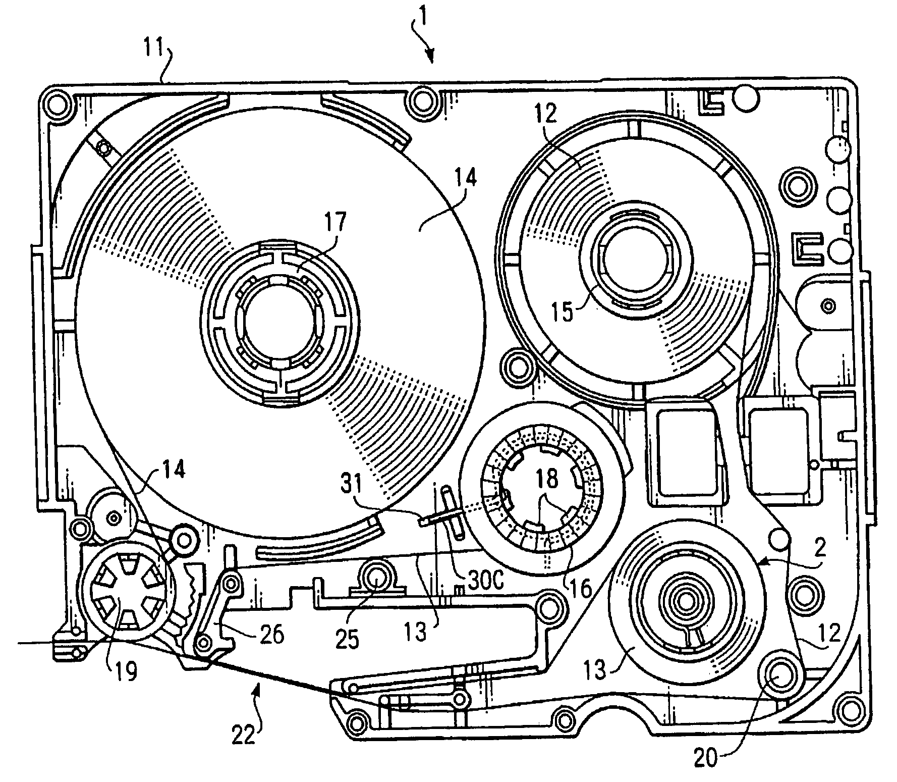
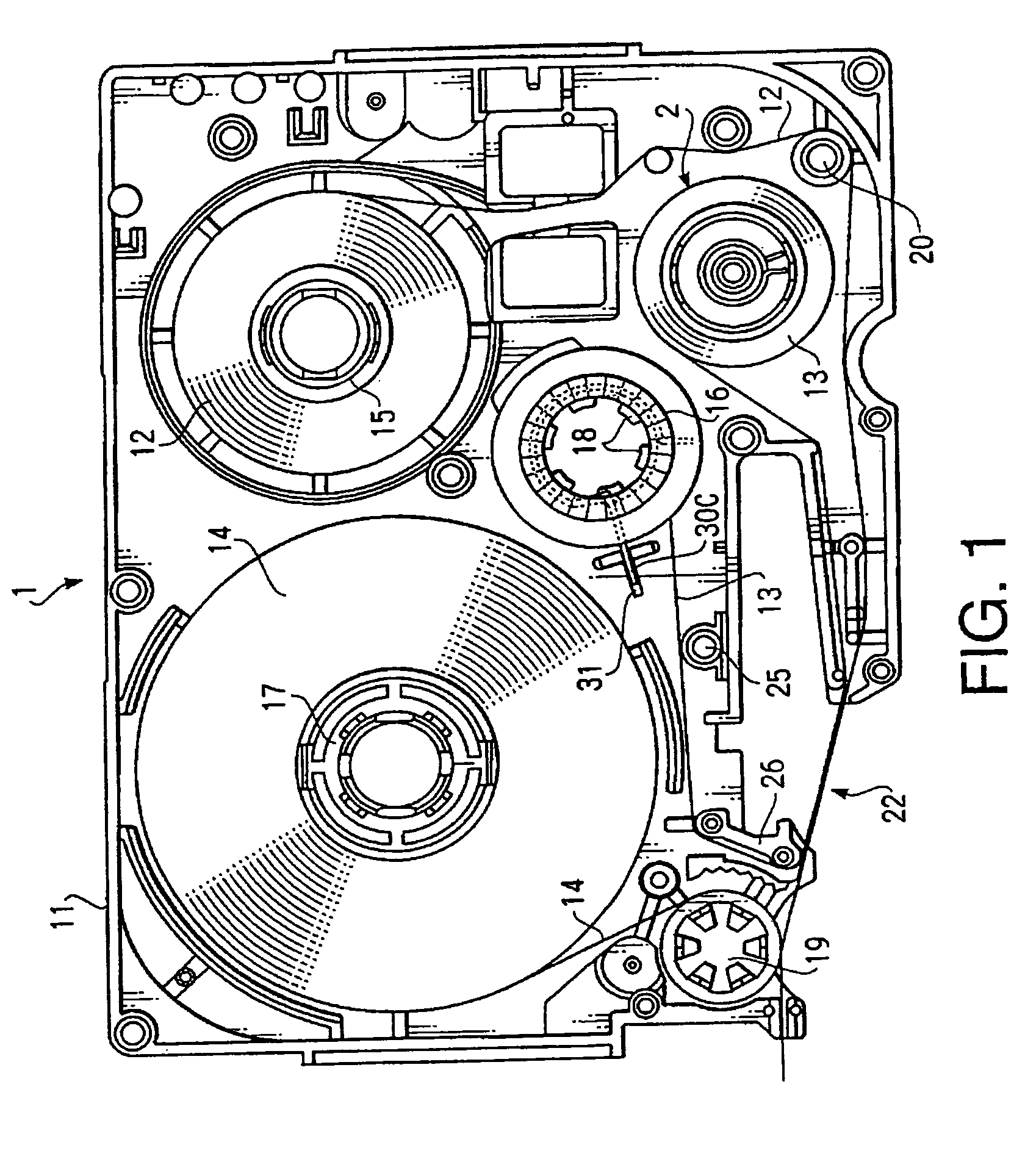
[0034]FIG. 1 shows an internal configuration of a tape cassette 1 embodying a ribbon cassette according to the embodiment of the invention. The tape cassette 1 is for use in a tape printing device (not shown) that prints on a long size print tape.

[0035]The tape cassette 1 includes a cassette case 11 made of resin, for example, and having a substantially rectangular parallelepiped form. Note that the cassette case 11 is composed of an upper part and a lower part and only the lower part is shown in FIG. 1. A clear tape 12, which is a medium to be printed, an ink ribbon 13 for printing on the clear tape 12, and a colored double-sided adhesive tape 14 to be adhered to the backside of the printed clear tape 12 are wound around respective spools and accommodated in the cassette case 11. A ribbon take up spool 16 for taking up the used ink ribbon 13 is also disposed in the casset...


PUM


Abstract

A ribbon cassette includes a ribbon supply spool, and a ribbon take up spool that takes up an ink ribbon from the ribbon supply spool by rotating in a first rotation direction. The ribbon take up spool is provided with an engaging portion including first and second walls arranged in the second rotation direction in this order. The first wall is defined along a plane including a rotation axis of the ribbon take up spool. The second wall is inclined to face outside the ribbon take up spool. The ribbon cassette further includes an engaging member. The engaging member resiliently engages with the engaging portion by dropping into a space defined between the first and second walls and thereby prevents the ribbon take up spool from rotating in a second rotation direction opposite to the first rotation direction. The engaging member, however, comes off from the engaging portion when the ribbon take up spool rotates in the first direction.

Description

BACKGROUND OF THE INVENTION[0001]The present invention relates to a ribbon cassette, and more particularly to a ribbon cassette provided with a ribbon supply spool, on which an ink ribbon is wound, a ribbon take up spool for taking up the ink ribbon from the ribbon supply spool, and a simple mechanism for preventing slack in the ink ribbon.[0002]Conventionally, many types of ribbon cassettes, each having a ribbon supply spool and a ribbon take up spool, are proposed. In such kind of ribbon cassettes, slack tends to occur in the ink ribbon since the ribbon supply spool is rotatably disposed in a ribbon cassette and no driving force is applied to the ribbon supply spool to regulate the rotation thereof. When the ribbon cassette is set into a printing device, the slack in the ink ribbon precludes suitable feeding of the ink ribbon from the ribbon cassette and hinders correct printing.[0003]Japanese Patent Application Provisional Publication No. HEI 8-25768 discloses a ribbon cassette t...

Claims


Application Information

Patent Timeline
IPC IPC(8): B41J35/28B41J32/00B41J31/00B41J32/02B41J33/52B41J35/08
CPCB41J35/08
Inventor HARADA, HIRONORIHORIUCHI, TAKASHI
Owner BROTHER KOGYO KK
Learn More