Working vehicle

a technology for working vehicles and skid steer loaders, which is applied in the direction of cranes, lifting devices, constructions, etc., can solve the problems of high cost, complex mechanism of above-described skid steer loaders, and difficulty in backing and turning operations of vehicles, so as to reduce grounding pressure and good running performance

Inactive Publication Date: 2006-10-31
YANMAR CO LTD
View PDF8 Cites 14 Cited by
  • Summary
  • Abstract
  • Description
  • Claims
  • Application Information

AI Technical Summary

Benefits of technology

[0014]Furthermore, according to the present invention, a pivot joint portion between the first arm and the vehicle body substantially corresponds to the rear end of an operation control portion, so that the bracket supporting the lift arm is positioned behind the operation control portion and prevented from obstructing an operator's side view. Furthermore, an operator's view from the operation control portion is highly improved when the lift arm is lifted up at the uppermost position thereof while securing an enough bucket reach.
[0023]Furthermore, a rubber crawler is employed for a traveling system of the working vehicle, whereby grounding pressure is decreased. Therefore, the vehicle can have good running performance even on a damp ground, or on a soft road.

Problems solved by technology

However, a big bracket sometimes obstructs an operator's rear or side view from the operation control portion so badly that the operator feels difficulty in backing and turning operation of the vehicle.
However, in each of the conventional skid steer loaders, the lift arm, while being lifted up, moves away from the vehicle body so as to have a bad influence on the skid steer loader in its fore-and-aft balance and its loading and dumping work, because the arm is integrally formed between its ends pivoted onto the bracket and the working machine, so as to have a constant angle bend.
Therefore, the vehicle tends to lose balance in dumping stuff loaded on the bucket onto a truck etc.
However, the above-described skid steer loader has a complex mechanism and is expensive in exchange for having a desired bucket locus because it needs additional elements, such as sensors for detecting a distance slid by the slidable arm and a tilt angle of the bucket, controllers for controlling the lift arm on the basis of detection values, and several control valves.

Method used


Image

  • Working vehicle
  • Working vehicle
  • Working vehicle

Examples


second embodiment

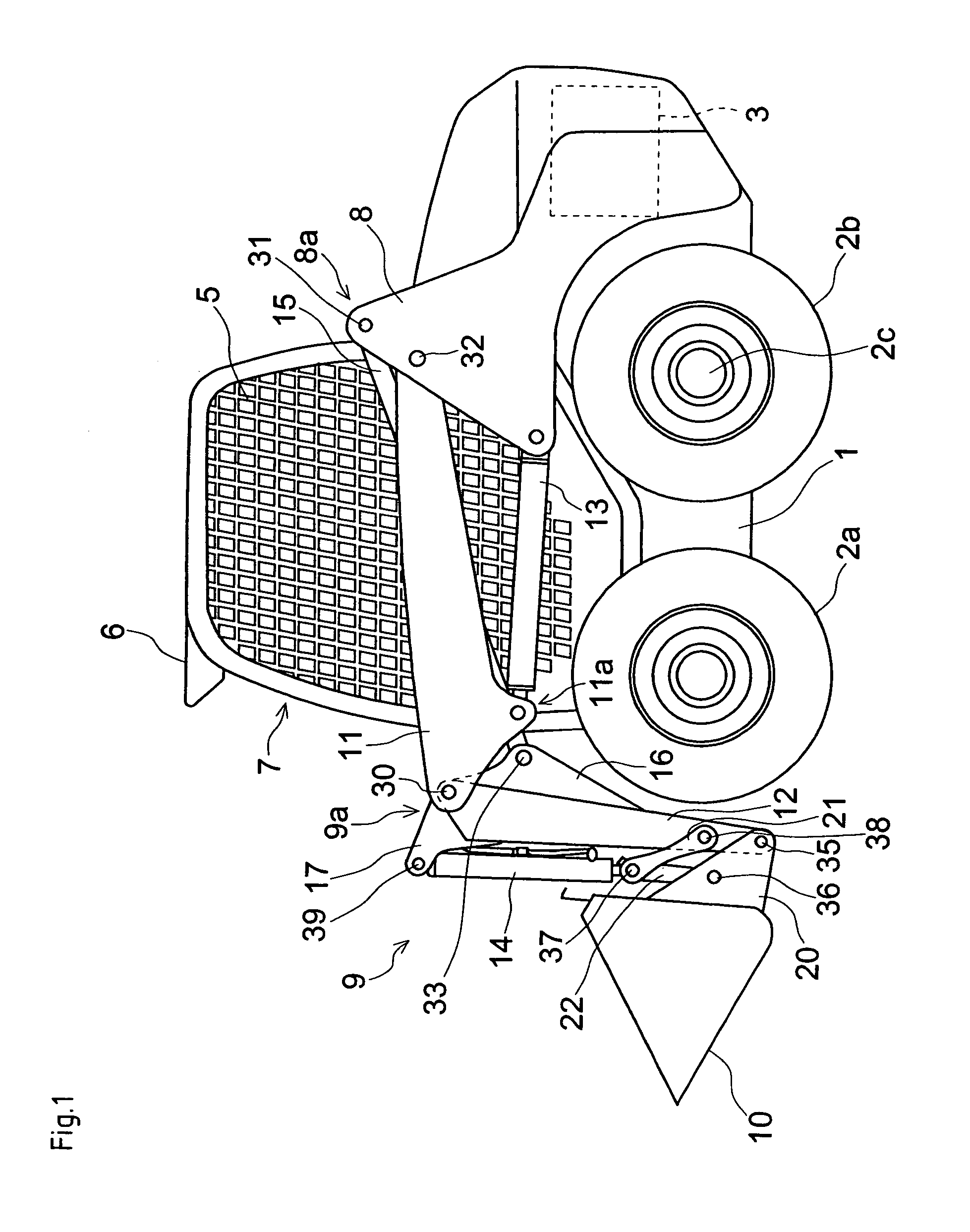
[0056]Next, description will be given of the lift arm structure.

[0057]In the present embodiment, as shown in FIG. 4, basal end portions of bucket cylinders 14 are fixed on tip ends of respective first arms 61.

[0058]To be more in detail, in the present embodiment, the tip end portion of each first arm 61 is inclined backward (forward-upward when not in operation), and the basal portion of each bucket cylinder 14 is pivoted onto the front end of first arm 61 with a pin 40, in comparison with the first embodiment, in which the basal portion of each bucket cylinder 14 is fixed onto stay 17, projecting forward from the basal portion of second arm 12. Furthermore, in the present embodiment, a second arm 62 is pivoted with a pin 41 onto a portion of first arm 61 slightly backward from the tip end thereof, and rod 15 is pivoted onto stay 16, projecting from the rear side of second arm 62, similar to stay 16 in the first embodiment.

first embodiment

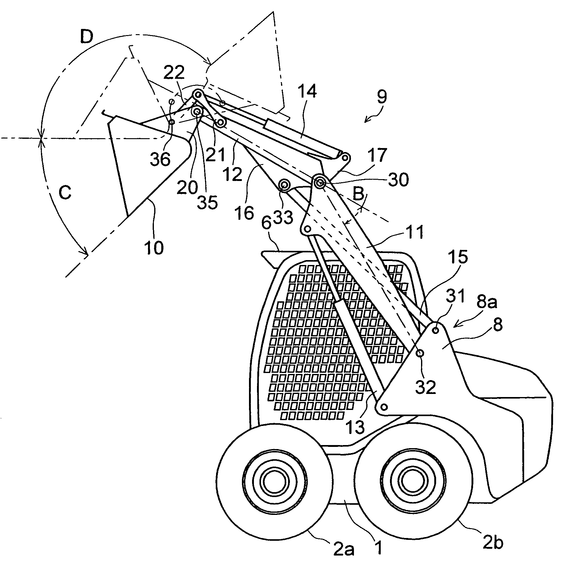
[0059]Due to this configuration, an angle of bend of each lift arm 9 is gradually decreased as first arm 61 is lifted up, similar to that in the Furthermore, since each bucket cylinder 14 is supported at the tip end of first arm 61, an opening of bucket 10 is turned upward following movement of lift arms 9 in the direction for decreasing the angle of bend thereof.

[0060]As described above, since each first arm 61 is provided with a portion for supporting one side of bucket cylinder 14, lift arm 9 can be lifted up keeping the opening of bucket 10 face almost upward in cooperation with change of the angle of bend formed by first arm 61 and second arm 62. This means that bucket 10 can be automatically leveled without any additional component.

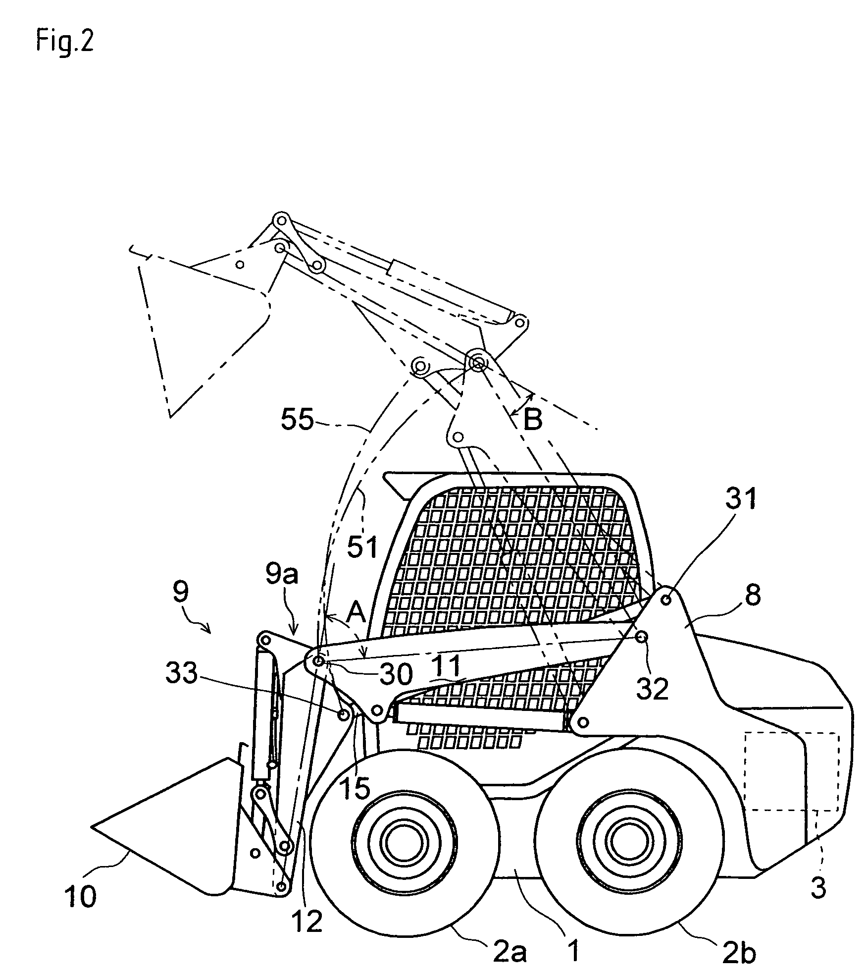
[0061]The angle of bend formed by arms 61 and 62 is controlled by driving cylinder 13 and by swing motion-limiting of rod 15, so that the position of lift arms 9 (position M in FIG. 4) during lifting-up can be brought closer to the body side. At th...


PUM


Abstract

A lift arm (9) includes a first arm (11) and a second arm (12). A pivot joint portion (32) where the first arm (11) is pivoted on a bracket (8) stood at a vehicle side portion substantially corresponds to the rear end of an operation control portion. A rod (15) as a swing motion-limiting member is interposed between the bracket (8) and the second arm (12). An angle of bend formed by the first arm (11) and the second arm (12) is set to be large at a lowered position of the lift arm and small at a lifted position.

Description

CROSS-REFERENCE TO RELATED APPLICATION[0001]The present application is a continuation of International Application No. PCT / JP2003 / 013396, filed on Oct. 20, 2003, designating the U.S., and claiming priority to JP 2002-306252, filed on Oct. 21, 2002.FIELD OF THE INVENTION[0002]The present invention relates to a working vehicle, such as a skid steer loader, which can work in a narrow space, and especially relates to a structure of lift arms extended forward from the rear part of the vehicle.BACKGROUND ART[0003]Conventionally, there is a well-known working vehicle called as a skid steer loader, which can turn on a small circle with driving wheels by operating steering levers provided in an operation control portion so as to carry out loading and dumping work in a limited space. Generally, the skid steer loader is equipped on a side portion thereof with a lift arm, which is formed in an approximate inverse L-shape in a side view, and extended forward from a rear portion of the vehicle. T...

Claims


Application Information

Patent Timeline
Patent Type & Authority Patents(United States)
IPC IPC(8): E02F3/38B66F9/00E02F3/34E02F3/342
CPCE02F3/3405E02F3/3414E02F3/342
Inventor YAMASHITA, MASAAKI
Owner YANMAR CO LTD
Why Eureka
Try Eureka