Gas supply system, substrate processing apparatus and gas supply method

a substrate processing and gas supply technology, applied in mechanical equipment, water supply installation, transportation and packaging, etc., can solve the problems of increasing the burden of control, requiring a large space for the lines, and unable to achieve the desired in-surface uniformity, etc., to achieve simple control operation and simple line configuration.

Inactive Publication Date: 2007-08-09
TOKYO ELECTRON LTD
View PDF15 Cites 46 Cited by
  • Summary
  • Abstract
  • Description
  • Claims
  • Application Information

AI Technical Summary

Benefits of technology

[0022]In accordance with the present invention, desired in-surface uniformity can be achieved by supplying a gas from plural portions in a processing chamber with a simple line configuration and a simple control operation without being affected by a pressure variation and the like.

Problems solved by technology

Accordingly, a line configuration and a flow rate control in each of the lines become complicated, which results in requiring a large space for the lines and an increased burden of control.
Further, even if the gases can be supplied from plural portions in the processing chamber by a simple control operation, when a flow rate ratio (distribution ratio) of the processing gases supplied to the plural portions changes due to a pressure variation, for example, during the introduction of the gases, the desired in-surface uniformity cannot be achieved.

Method used


Image

  • Gas supply system, substrate processing apparatus and gas supply method
  • Gas supply system, substrate processing apparatus and gas supply method
  • Gas supply system, substrate processing apparatus and gas supply method

Examples


first embodiment

Configuration Example of Substrate Processing Apparatus in Accordance with a First Embodiment

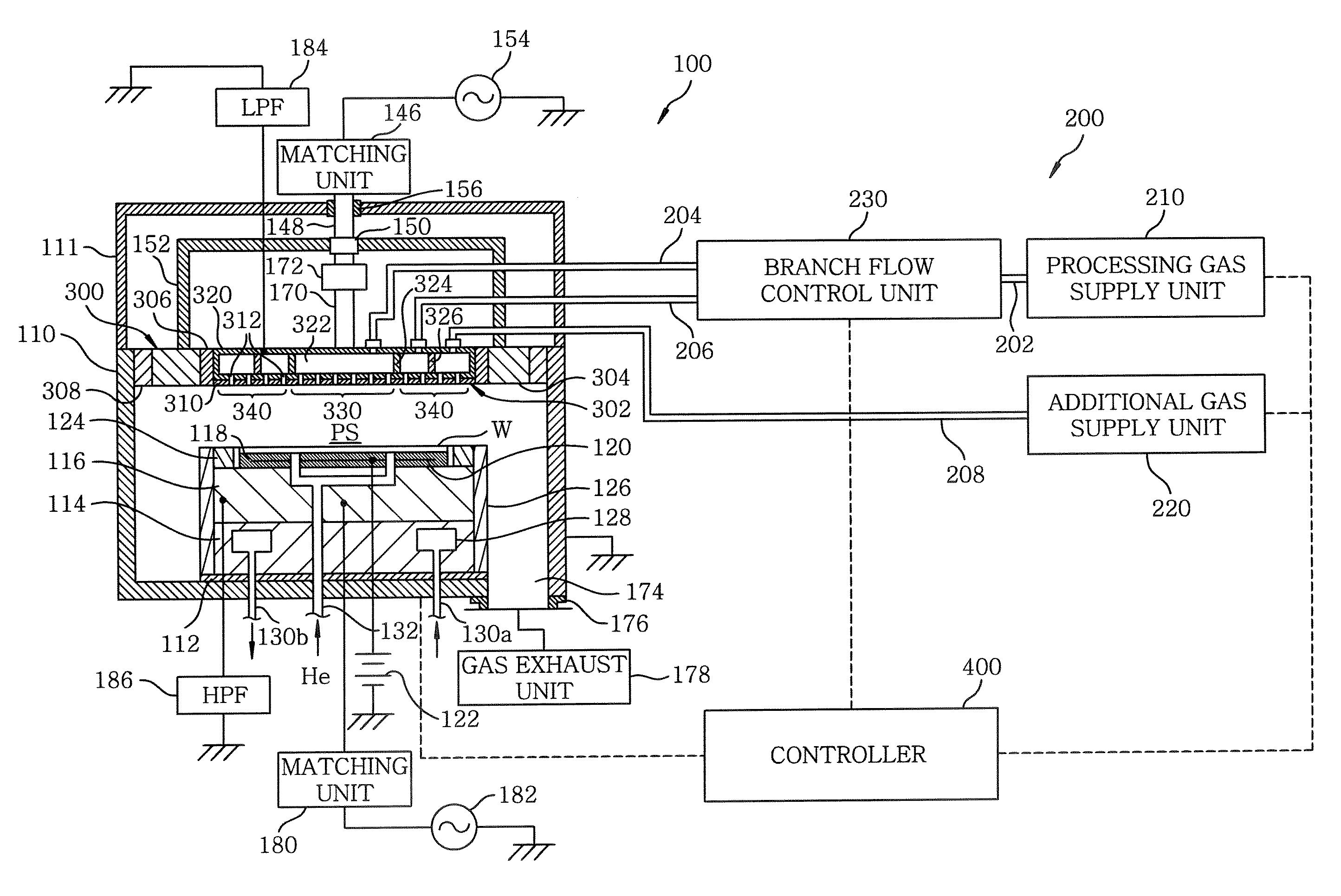
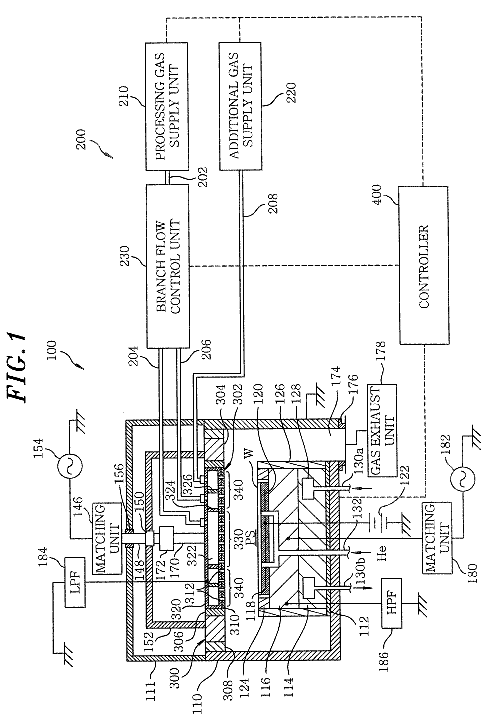
[0034]First of all, a substrate processing apparatus in accordance with a first embodiment of the present invention will be described with reference to FIG. 1. FIG. 1 is a cross sectional view showing a schematic configuration of the substrate processing apparatus in accordance with the first embodiment of the present invention. Herein, the substrate processing apparatus is configured as a parallel plate type plasma etching apparatus.

[0035]Such a substrate processing apparatus 100 includes a processing chamber 110 formed of a substantially cylindrical processing vessel. The processing vessel is made of aluminum alloy, for example, and is electrically grounded. Further, an inner wall surface of the processing vessel is coated with an alumina film or an yttrium oxide (Y2O3) film.

[0036]Disposed inside the processing chamber 110 is a susceptor 116 forming a lower electrode serving also as a moun...

second embodiment

Exemplary Configuration of Substrate Processing Apparatus in Accordance with Second Embodiment

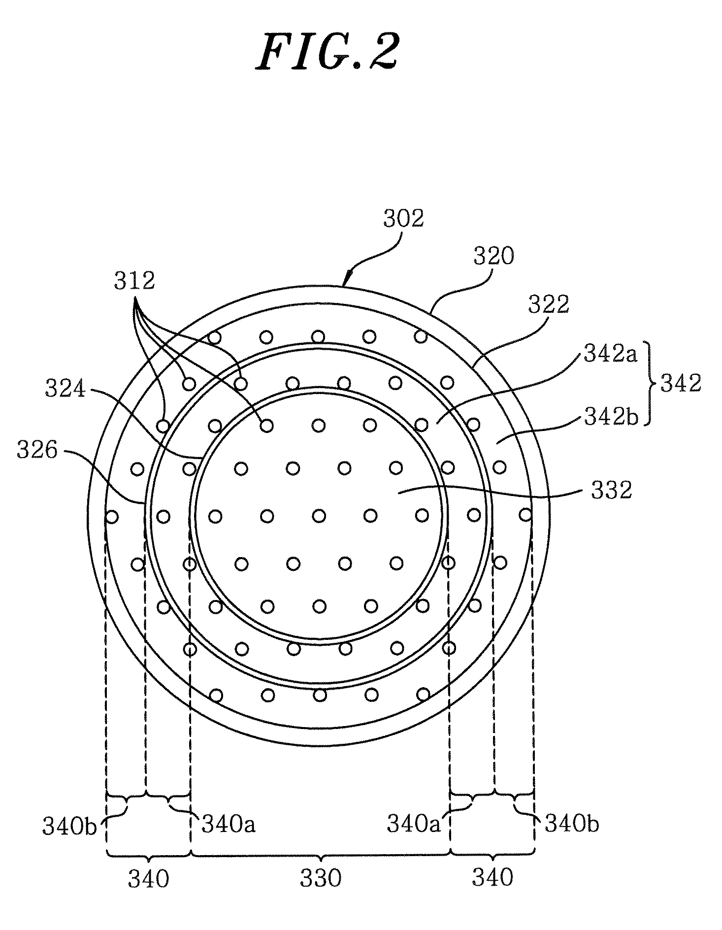
[0098]Hereinafter, a substrate processing apparatus 101 in accordance with a second embodiment of the present invention will be described with reference to drawings. FIG. 7 provides a block diagram of an exemplary configuration of the gas supply system 201 of the substrate processing apparatus 101 in accordance with the second embodiment of the present invention. FIG. 8 depicts a transversal cross sectional view of the inner upper electrode 302 forming the shower head in accordance with this embodiment.

[0099]Although, in the first embodiment, the second gas introduction section 340 for supplying a gas toward the edge region of the wafer W is divided into the processing gas introduction section 340a and the additional gas introduction section 340b, the second embodiment has a configuration in which the first gas introduction section 330 for supplying a gas toward the central region of the wa...


PUM

PropertyMeasurementUnit
frequencyaaaaaaaaaa
frequencyaaaaaaaaaa
frequencyaaaaaaaaaa

Abstract

A gas supply system includes a first and a second branch line branched from a processing gas supply line to be respectively connected with a first and a second gas introduction section for introducing a gas from different portions in a processing chamber and a branch flow control unit for controlling branch flows of the processing gas distributed from the processing gas supply line to the first and the second branch line based on pressures in the first and the second processing gas branch line. The gas supply system further includes an additional gas supply unit for supplying an additional gas and an additional gas supply line for allowing the additional gas to flow therein. The first or second gas introduction section is divided into a processing gas introduction section connected with the branch lines and an additional gas introduction section connected with the additional gas supply line.

Description

FIELD OF THE INVENTION[0001]The present invention relates to a gas supply system for supplying a gas into a processing chamber, a substrate processing apparatus and a gas supply method.BACKGROUND OF THE INVENTION[0002]A substrate processing apparatus is configured to perform specific processes such as a film forming process, an etching process and the like on a substrate to be processed (hereinafter, simply referred to as “substrate”) such as a semiconductor wafer, a liquid crystal substrate or the like.[0003]As for such a substrate processing apparatus, there has been known a plasma processing apparatus, for example. The plasma processing apparatus includes, inside a processing chamber, a lower electrode serving also as a mounting table for mounting thereon a substrate and an upper electrode serving also as a shower head for injecting a gas toward the substrate. Such a parallel plate type plasma processing apparatus is configured to perform specific processes such as a film forming...

Claims


Application Information

Patent Timeline
Patent Type & Authority Applications(United States)
IPC IPC(8): F17D1/00
CPCC23C16/45565H01J37/3244F17D1/04C23C16/45574Y10T137/0318
Inventor MIZUSAWA, KENETSU
Owner TOKYO ELECTRON LTD
Why Eureka
Try Eureka