Endoscope apparatus

a technology of endoscope and endoscope, which is applied in the field of endoscope equipment, can solve the problems that the original capabilities of the machine cannot be fulfilled in some cases, and the endoscope unit cannot be attached/detachable with respect to the fixed unit,

Inactive Publication Date: 2006-10-31
OLYMPUS OPTICAL CO LTD
View PDF13 Cites 67 Cited by
  • Summary
  • Abstract
  • Description
  • Claims
  • Application Information

AI Technical Summary

Problems solved by technology

When the position of the connector portion does not agree with that of the socket because of fluctuation by assembly during manufacturing, there is a problem that the scope unit cannot be attached/detached with respect to the fixed unit.
Furthermore, when the scope units cannot securely be positioned with respect to the fixed unit, loss of an illuminative light amount, or cont

Method used


Image

  • Endoscope apparatus
  • Endoscope apparatus
  • Endoscope apparatus

Examples


first embodiment

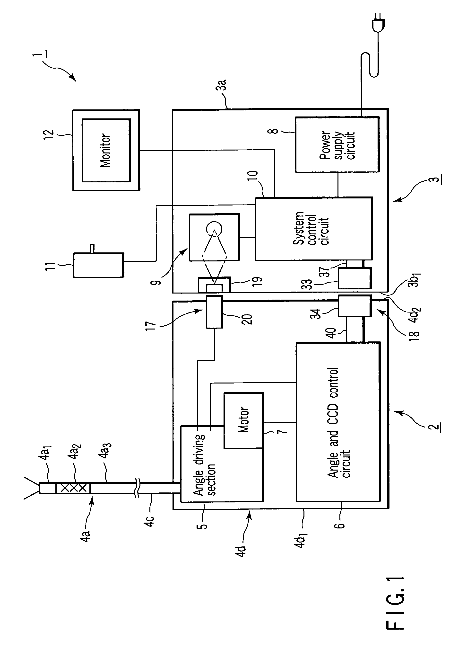
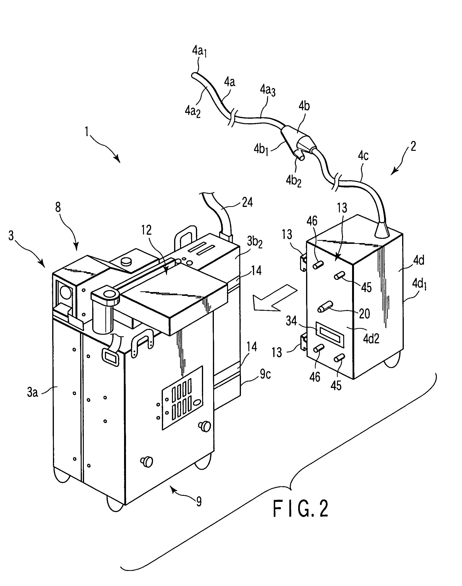
[0154]Then, the above-described constitution produces the following effects. That is, in the endoscope apparatus 1 of the present embodiment, the LED 85 is disposed on the tip-end surface of the head portion 4a1 of the scope unit 2, this LED 85 is used as the light source of the illuminative light, and therefore the light source unit 9 which has been required in the first embodiment is unnecessary. Therefore, the fixed unit 3 which is an external apparatus separate from the scope unit 2 can further be miniaturized / lightened, and an attachment / detachment mechanism of the base unit 4d of the scope unit 2 to the fixed unit 3 can be simplified.

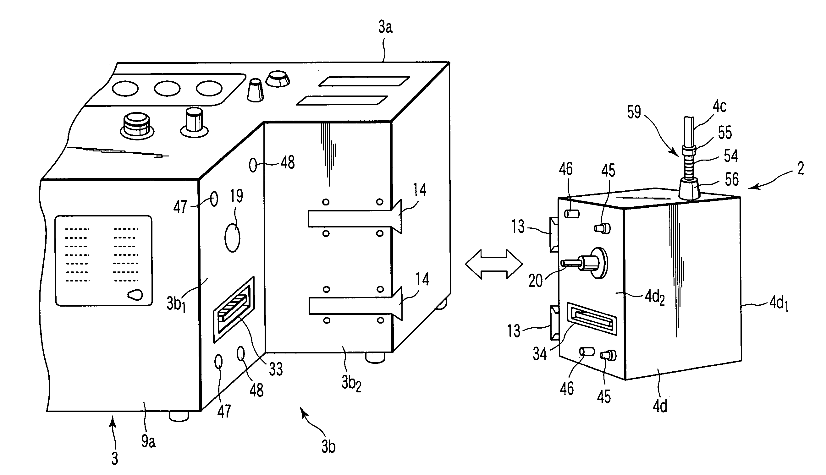
[0155]Moreover, FIG. 26 shows a third embodiment of the present invention. In the present embodiment, the constitutions of the connectors 33 and 34 of the endoscope apparatus 1 of the first embodiment (see FIGS. 1 to 24) are changed as follows. It is to be noted that the basic constitution of the endoscope apparatus 1 of the present embodiment is ...

third embodiment

[0166]FIG. 27 shows a modification example of the

[0167]In the above-described third embodiment, the play portion 98 at the time of the attaching of the scope side connector 92 to the end plate 4d2 of the unit case 4d1 is disposed, but in this modification example, a play portion 99 also at the time of the fixing of the connector main body 94 to the scope unit connection surface 3b1 is disposed.

[0168]A bore diameter of the screw insertion hole 94c on the connector main body 94 side is formed to be larger than the diameter of the screw portion of the fixing screw 95, and a gap between the screw portion and the screw insertion hole 94c is disposed as the play portion 99. By this constitution, when the connector main body 94 is fixed to the scope unit connection surface 3b1 by the fixing screw 95, the backlash is disposed in the connector main body 94 by the range of the play portion 99.

[0169]By this constitution, since the play portion 98 of the connector main body 96 and the play port...

fourth embodiment

[0175]FIG. 29 shows a modification example of the

[0176]The monitor 12 of the fixed unit 123 in the above-described fourth embodiment shows an example in which a frame (pipe) 124 is used to constitute the monitor separately from the fixed unit main body, but this modification example is an example in which the monitor is disposed as a built-in monitor 124 in the fixed unit 123 main body. When the monitor 12 is built in the fixed unit main body, the fixed unit can be miniaturized, and is easily carried. Since the built-in monitor 124 is disposed, center of gravity of the fixed unit 123 is lowered to improve balance, and the connection operation with respect to the scope unit 122 is facilitated.


PUM


Abstract

An endoscope apparatus includes at least one of a connector on the side of a scope unit and a connector on the side of a fixed unit in a connector portion disposed in an detachable portion of a base unit and the fixed unit of the scope unit is a movable connector, and in the detachable portion, the base unit is connected to the fixed unit by positioning means for positioning the fixed unit side to the base unit side, when the connector on the fixed unit side is connected to that on the base unit side.

Description

CROSS-REFERENCE TO RELATED APPLICATIONS[0001]This application is based upon and claims the benefit of priority from prior Japanese Patent Application No. 2002-265724, filed Sep. 11, 2002, the entire contents of which are incorporated herein by reference.BACKGROUND OF THE INVENTION[0002]The present invention relates to an endoscope apparatus which is used in an industrial field and which is inserted into an inspection object space such as a pipe to observe the inside of the inspection object space, and the like.[0003]As a general endoscope apparatus, a constitution described, for example, in Jpn. Pat. Appln. KOKAI Publication No. 7-181400 is known. In this publication, an operation portion on a hand side is connected to a base end of an elongated insertion portion inserted into the inspection object space. Furthermore, an observation optical system including an image pickup device for observation, an illuminating window for irradiation with an illuminative light, and the like are dis...

Claims


Application Information

Patent Timeline
IPC IPC(8): A61B1/01A61B1/00A61B1/04
CPCA61B1/00105A61B1/042A61B1/00121
Inventor SARUYA, NOBUYUKI
Owner OLYMPUS OPTICAL CO LTD
Why Eureka
Try Eureka