Endoscope device

a technology of endoscope and endoscope, which is applied in the field of endoscope devices, can solve the problems that the information of deep tissue near the surface of living body tissue cannot be readily recognized, and achieves the effect of improving the accuracy of endoscope results

Inactive Publication Date: 2008-11-27
OLYMPUS CORP
View PDF19 Cites 77 Cited by
  • Summary
  • Abstract
  • Description
  • Claims
  • Application Information

AI Technical Summary

Problems solved by technology

That is, with overlapped RGB light, there is a problem that desired deep tissue information near the surface of the tissue of the living body tissue cannot be readily recognized, since a broad range of the deep tissue information is taken into the image-pickup signals of the light of each wavelength region.

Method used


Image

  • Endoscope device
  • Endoscope device
  • Endoscope device

Examples


first embodiment

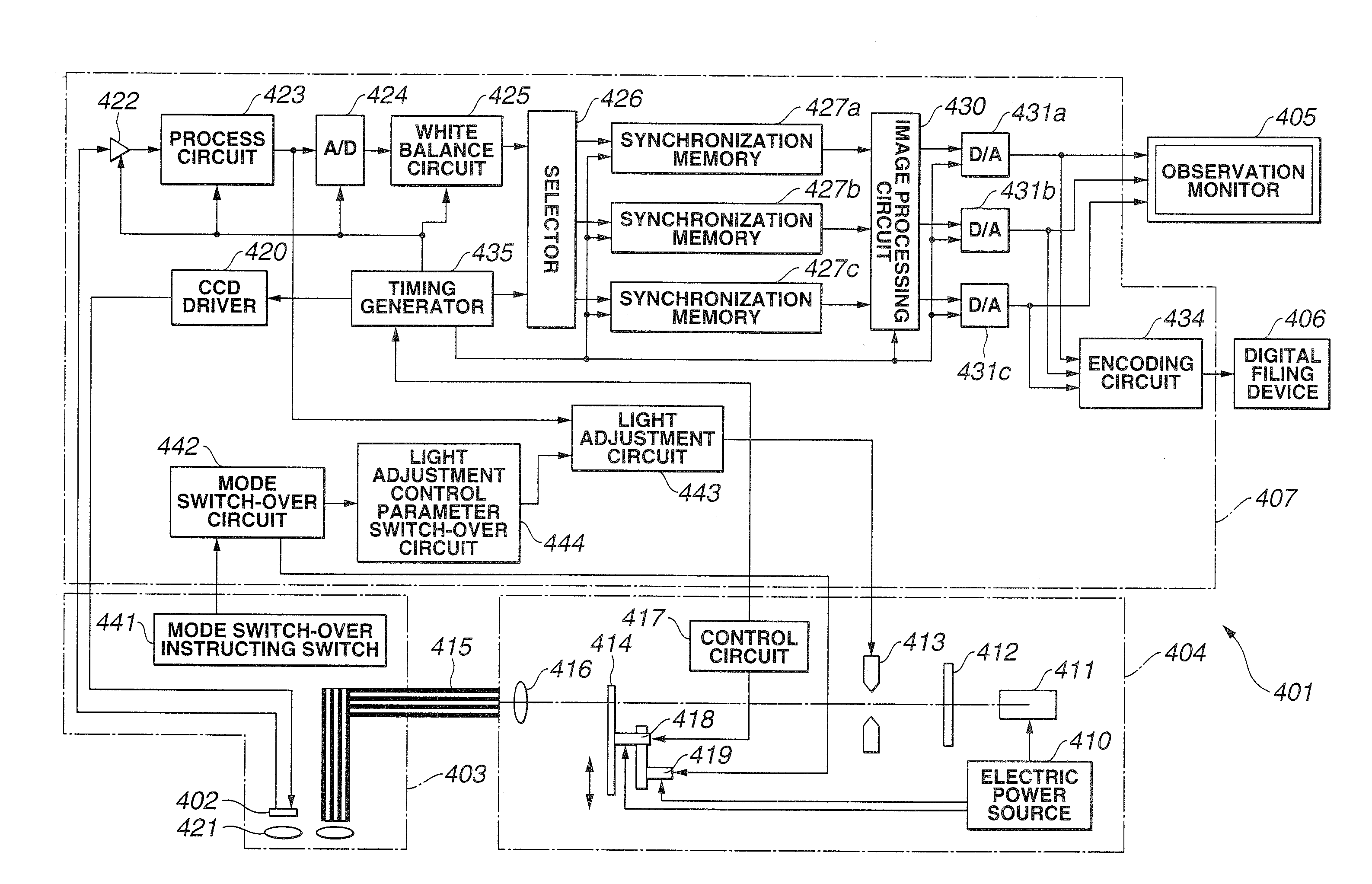
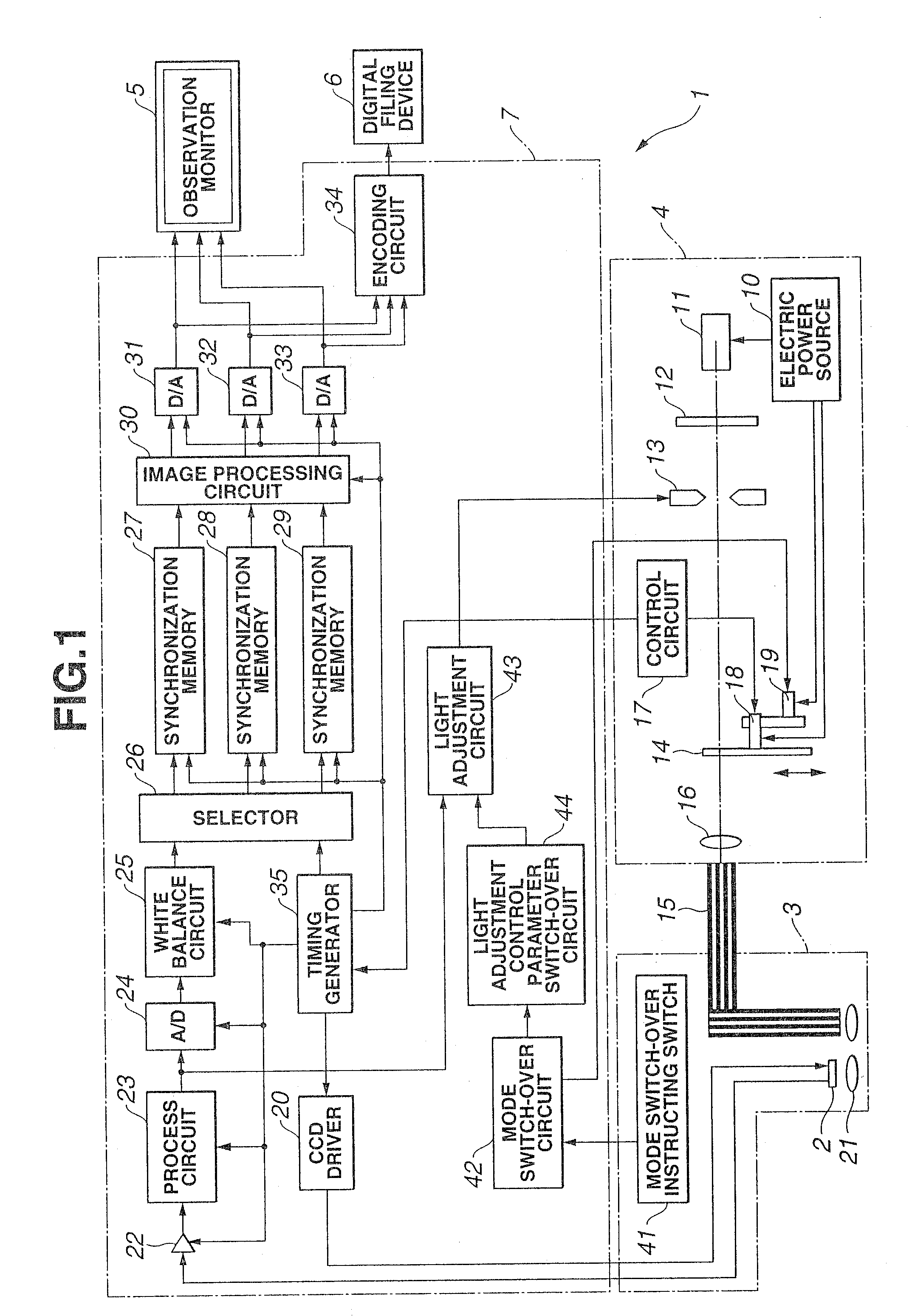
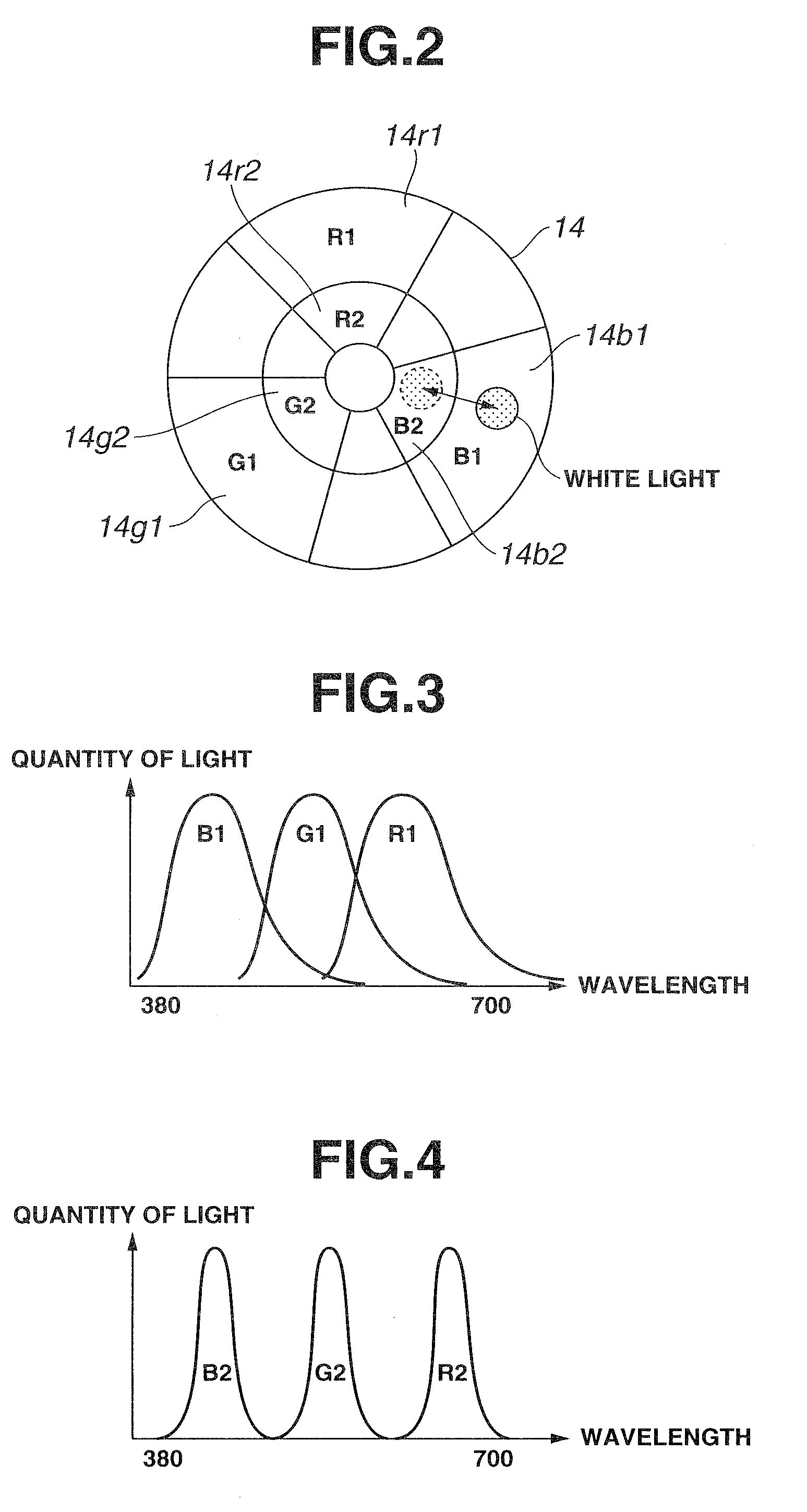
[0116]First, the present invention will be described with reference to FIG. 1 through FIG. 33. Here, FIG. 1 is a configuration diagram illustrating the configuration of an endoscope device, FIG. 2 is a configuration diagram illustrating the configuration of a rotating filter shown in FIG. 1, FIG. 3 is a diagram illustrating the spectral properties of a first filter set of the rotating filter shown in FIG. 2, FIG. 4 is a diagram illustrating the spectral properties of a second filter set of the rotating filter shown in FIG. 2, FIG. 5 is a diagram illustrating the structure of the living body tissue in the layer direction to be observed with the endoscope device shown in FIG. 1, FIG. 6 is a diagram describing the state of the illumination light from the endoscope device shown in FIG. 1 reaching the living body tissue in the layer direction, FIG. 7 is a diagram illustrating each of the band images from frame sequence light transmitted through the first filter set shown in FIG. 3, FIG. ...

second embodiment

[0164]Next, the present invention will be described with reference to FIG. 34 through FIG. 36.

[0165]FIG. 34 is a configuration diagram illustrating the configuration of an endoscope device, FIG. 35 is a configuration diagram illustrating the configuration of the rotating filter shown in FIG. 34, and FIG. 36 is a diagram illustrating the spectral properties of the color chip shown in FIG. 34.

[0166]The second embodiment is almost the same as the first embodiment, so only the differing points will be described, and the same configurations will be denoted with the same reference numerals and description thereof will be omitted.

[0167]As shown in FIG. 34, with the electronic endoscope 3 according to the present embodiment, a color chip 81 is disposed on the front face of the CCD 2, thereby making up a color CCD 2a, configuring an endoscope device 1 of a synchronous system when performing normal observation. Color image signals from the color CCD 2a are converted into color image data at t...

third embodiment

[0172]Next, the present invention will be described with reference to FIG. 37 through FIG. 46.

[0173]FIG. 37 is a configuration diagram illustrating the configuration of an endoscope device, FIG. 38 is a diagram illustrating the band-pass properties of the band restricting filter shown in FIG. 37, FIG. 39 is a diagram illustrating the spectral properties of discrete narrow-band frame sequence light obtained by the band restricting filter shown in FIG. 38, FIG. 40 is a diagram illustrating the band-pass properties of a first modification made on the band restricting filter shown in FIG. 37, FIG. 41 is a diagram illustrating the spectral properties of discrete narrow-band frame sequence light from the band restricting filter shown in FIG. 40, FIG. 42 is a diagram illustrating the band-pass properties of a second modification made on the band restricting filter shown in FIG. 37, FIG. 43 is a diagram illustrating an example of spectral properties of the xenon lamp shown in FIG. 37, FIG. ...


PUM


Abstract

An endoscope device obtains tissue information of a desired depth near the tissue surface. A xenon lamp (11) in a light source (4) emits illumination light. A diaphragm (13) controls a quantity of the light that reaches a rotating filter. The rotating filter has an outer sector with a first filter set, and an inner sector with a second filter set. The first filter set outputs frame sequence light having overlapping spectral properties suitable for color reproduction, while the second filter set outputs narrow-band frame sequence light having discrete spectral properties enabling extraction of desired deep tissue information. A condenser lens (16) collects the frame sequence light coming through the rotating filter onto the incident face of a light guide (15). The diaphragm controls the amount of the light reaching the filter depending on which filter set is selected.

Description

CROSS REFERENCE TO RELATED APPLICATIONS[0001]The present application is a continuation application of (1) U.S. application Ser. No. 10 / 333,155 filed on Jan. 16, 2003, which claims priority based on (2) Japanese Patent Application No. 2000-221312 applied in Japan on Jul. 21, 2000, (3) Japanese Patent Application No. 2000-227237 applied in Japan on Jul. 27, 2000, (4) Japanese Patent Application No. 2000-227238 applied in Japan on Jul. 27, 2000, and (5) Japanese Patent Application No. 2001-88256 applied in Japan on Mar. 26, 2001 claiming priority based on the aforementioned Japanese Patent Application No. 2000-221312 applied in Japan on Jul. 21, 2000, and the contents disclosed in the aforementioned (1) through (5) have been referenced to in the present specification, Claims, and drawings and are incorporated herein by reference.TECHNICAL FIELD[0002]The present invention relates to an endoscope device which captures images of living body tissue and performs signal processing thereon.BA...

Claims


Application Information

Patent Timeline
Patent Type & Authority Applications(United States)
IPC IPC(8): A61B1/045A61B1/04A61B1/06A61B5/00
CPCA61B1/043A61B1/0638A61B1/0646A61B1/0669A61B5/0071A61B5/0084A61B1/063A61B1/000094A61B1/0655
Inventor GONO, KAZUHIRONONAMI, TETSUO
Owner OLYMPUS CORP
Why Eureka
Try Eureka