Endoscope apparatus and image processing apparatus

a technology of endoscope and image processing, which is applied in the field of endoscope apparatus and image processing apparatus, can solve the problems of limiting the light irradiation of a subject, putting a heavy burden on both patients and doctors, and limiting the beam incident to the solid-state image pickup devi

Active Publication Date: 2009-05-07
OLYMPUS CORP
View PDF25 Cites 69 Cited by
  • Summary
  • Abstract
  • Description
  • Claims
  • Application Information

AI Technical Summary

Benefits of technology

[0016]An image processing apparatus according to a third aspect of the present invention comprises: image pickup means that performs image pickup on a subject and outputs an image pickup signal based on the picked up subject picture; one or more storing means that stores an image pickup signal outputted from the image pickup means; write signal generating means that outputs to the storing means a write signal that causes the storing means to store the image pickup signal; switching signal generating means that outputs to the image pickup means and the storing means a switching signal for switching between a first observation mode that creates a first observation image based on an image pickup signal outputted from the image pickup means and a second observation mode that creates a second observation image that differs from the first observation signal based on an image pickup signal outputted from the image pickup means; write inhibiting means that causes writing of the image pickup signal to the storing means to be suspended by stopping output of the write signal based on the switching signal; and write inhibition releasing means that releases suspension of writing of the image pickup signal to the storing means by restarting output of the write signal to the storing means when a predetermined time has elapsed after output of the switching signal.
[0017]An image processing apparatus according to a fourth aspect of the present invention comprises: one or more image pickup means that performs image pickup on a subject and outputs an image pickup signal based on the picked up subject picture; one or more storing means that stores an image pickup signal outputted from the image pickup means; write signal generating means that outputs to the storing means a write signal that causes the storing means to store the image pickup signal; light source means that irradiates the subject with an illumination light having a first band and an illumination light having a second band that differs from the second illumination light; switching signal generating means that outputs to the image pickup means and the storing means a switching signal for switching between a first observation mode in which, when an illumination light having the first band is irradiated to the subject, image picku...

Problems solved by technology

With a conventional apparatus such as that disclosed in Japanese Patent Laid-Open No. 4-150845, illumination light irradiating a subject is limited to excitation light and light beams incident to the solid state image pickup device is limited to fluorescence.
Therefore, conventionally, every time an endoscopic observation is performed in order to visually observe positions or conditions of a diseased part, it is required that an endoscope apparatus for fluorescence observation be replaced with an endoscope apparatus for normal light observation and vice versa for alternate use, thereby placing a heavy burden on both patients and doctors.
However, with such an apparatus, although both a normal light observation image and a fluorescence observation image are displayable on a monitor, a normal light observation image and a fluorescence observation image picked up at the same timing cannot be observed simultaneously.
This creates a problem in that it is difficult to compare a normal light observation image and a fluorescence observation image, such as, for example, the same region cannot be observed when a subject moves during switching of observation images.
In addition, another problem exists in that, when di...

Method used


Image

  • Endoscope apparatus and image processing apparatus
  • Endoscope apparatus and image processing apparatus
  • Endoscope apparatus and image processing apparatus

Examples


first embodiment

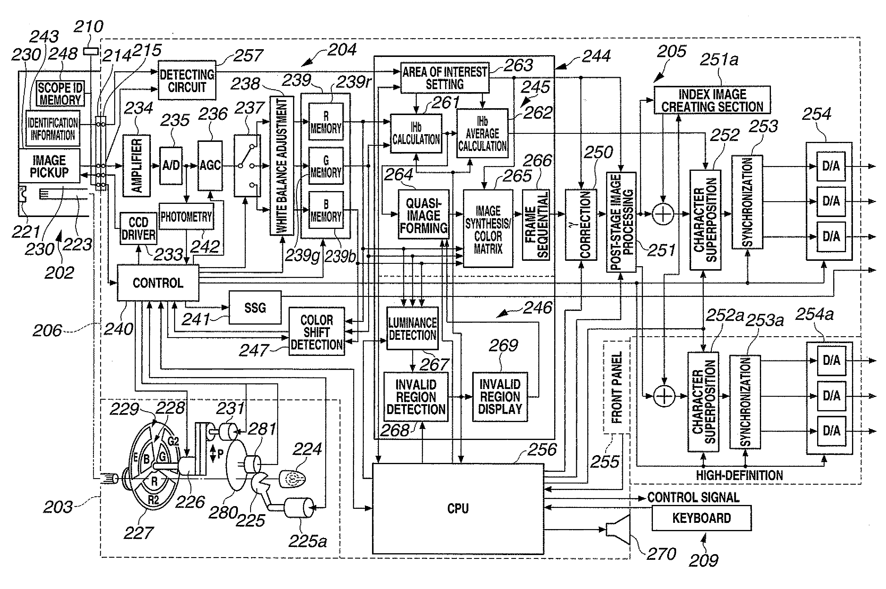
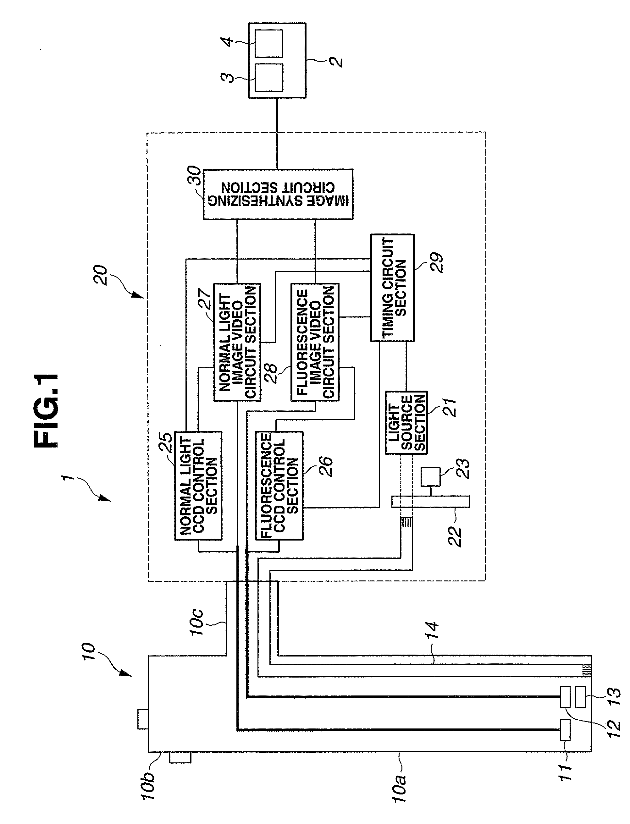
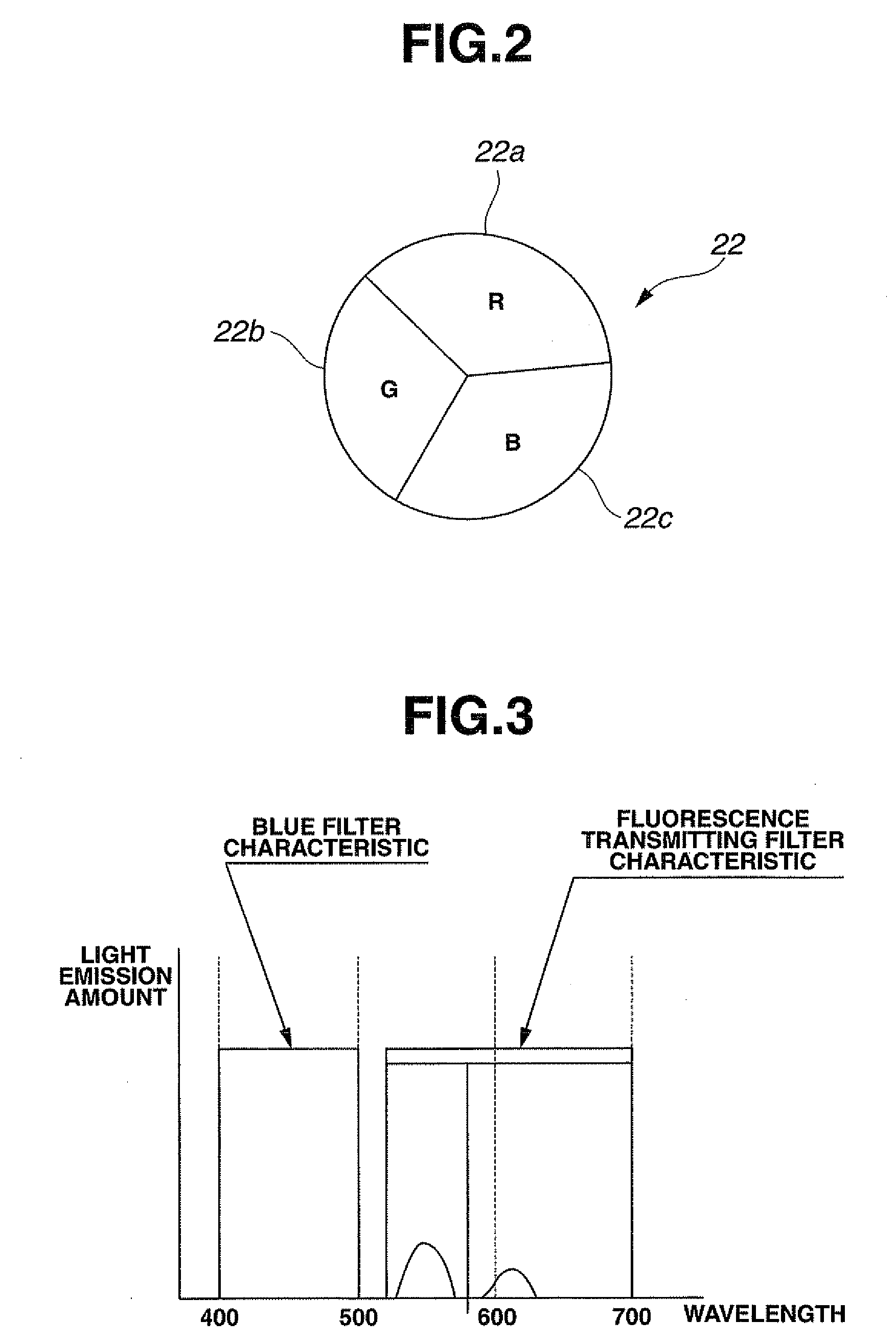
[0070]In FIG. 1, reference numeral 1 denotes an endoscope apparatus. The endoscope apparatus 1 comprises: an electronic endoscope 10 capable of normal light observation of a subject under visible light and fluorescence observation under fluorescence emitted by the subject; and a video processor 20 as an image processing apparatus that drives the electronic endoscope 10 and performs signal processing on a normal light observation picture and a fluorescence observation picture picked up by the electronic endoscope 10 to create a normal light image and a fluorescence image. A monitor 2 is connected to the video processor 20. A normal light observation image 3 and a fluorescence observation image 4 are displayed on a screen of the monitor 2.

[0071]The electronic endoscope 10 comprises a flexible insertion portion 10a to be inserted into a body cavity or the like and an operation section 10b provided at a proximal end side of the insertion portion 10a, and is connected to the video proces...

second embodiment

[0095]Next, a second embodiment of the present invention will be described. In contrast to the first embodiment described above, the second embodiment is provided with an illumination system that outputs blue excitation light for fluorescence observation which is a separate system to the illumination system for normal light observation. Note that members and circuit sections that perform like operations as the first embodiment are assigned like reference characters, and that descriptions thereof will be omitted.

[0096]As shown in FIG. 4, an endoscope apparatus 40 according to the second embodiment comprises: an electronic endoscope 50 capable of normal light observation and fluorescence observation; and a video processor 60 that drives the electronic endoscope 50, performs signal processing on a normal light observation picture and a fluorescence observation picture from the electronic endoscope 50, and displays a normal light observation image and a fluorescence observation image on...

third embodiment

[0107]Next, a third embodiment of the present invention will be described. Compared to the second embodiment, the objective optical system of the fluorescence CCD 12 of the electronic endoscope 50 has been changed for the third embodiment, and in accordance with the change in the objective optical system, a portion of the functions of the video processor 60 has been changed. Hereinafter, members and circuit sections that perform like operations as the first and second embodiments are assigned like reference characters, and descriptions thereof will be omitted.

[0108]As shown in FIG. 6, an endoscope apparatus 70 according to the third embodiment comprises: an electronic endoscope 80 capable of normal light observation and fluorescence observation; and a video processor 90 that drives the electronic endoscope 80, performs signal processing on a normal light observation picture and a fluorescence observation picture from the electronic endoscope 80, and displays a synthesized image on t...


PUM


Abstract

A normal light CCD 11 is driven via a normal light CCD control section 25 by a timing signal from a timing circuit section 29 of a video processor 20. At the same time, a fluorescence CCD 12 is driven via a fluorescence CCD control section 26. Then, an image pickup signal according to an RGB frame sequential method from the normal light CCD 11 is processed by a normal light image video circuit section 27 and a normal color image is created while an image pickup signal from the fluorescence CCD 12 is processed by a fluorescence image video circuit section 28, and an image pickup signal of a subject excited by blue illumination light and transmitted through a fluorescence transmitting filter 13 is extracted to create a fluorescence image of the subject. The normal color image and the fluorescence image of the subject are synthesized by an image synthesizing circuit section 30 and outputted to a monitor 2, whereby the normal light image and the fluorescence image is displayed side by side or on top of each other.

Description

TECHNICAL FIELD[0001]The present invention relates to an endoscope apparatus and an image processing apparatus capable of obtaining observation images under normal light and observation images under fluorescence.BACKGROUND ART[0002]Observation of living tissue by an endoscope includes, in addition to normal endoscopic observation using visible light, fluorescence observation in which fluorescence pictures are observed by irradiating excitation light. The fluorescence observation utilizes a characteristic in which, when light (excitation light) whose wavelength falls within 400 nm to 480 nm is irradiated to living tissue, normal tissue intensely emits fluorescence in the range of approximately 480 nm to 630 nm while fluorescence from diseased parts such as carcinoma cells is weaker, and is known as a technique that enables discovery of abnormal regions such as early cancer that are difficult to view under normal endoscopic observation.[0003]Conventionally, as disclosed in Japanese Pa...

Claims


Application Information

Patent Timeline
IPC IPC(8): A61B1/04A61B1/06
CPCA61B1/043A61B1/045G01N21/6486A61B5/0084G01N21/6456A61B5/0071G02B23/24H04N5/91H04N23/00
Inventor TAKASUGI, KEIKANEKO, KAZUMA
Owner OLYMPUS CORP
Why Eureka
Try Eureka