
Watch with fly back hand function and corresponding fly back hand mechanism

a technology of a watch and a back hand, applied in the field of watches, can solve the problems of not being able to directly being time-consuming and disruptive, and being difficult to use such a manual device. , to achieve the effect of affecting the reading process of normal time indication, and being difficult to read the absolute time of the start or end of an even

Inactive Publication Date: 2006-10-31
RICHEMONT INT
View PDF5 Cites 14 Cited by
  • Summary
  • Abstract
  • Description
  • Claims
  • Application Information

AI Technical Summary

Benefits of technology

[0010]The objective of this invention is to make a watch both for normal time indication as well as for effective and simple measurement of time differences respectively for reading the durations of various events while avoiding the aforementioned disadvantages of the current systems, and the implementation of a fly back hand mechanism which is suitable for this purpose.
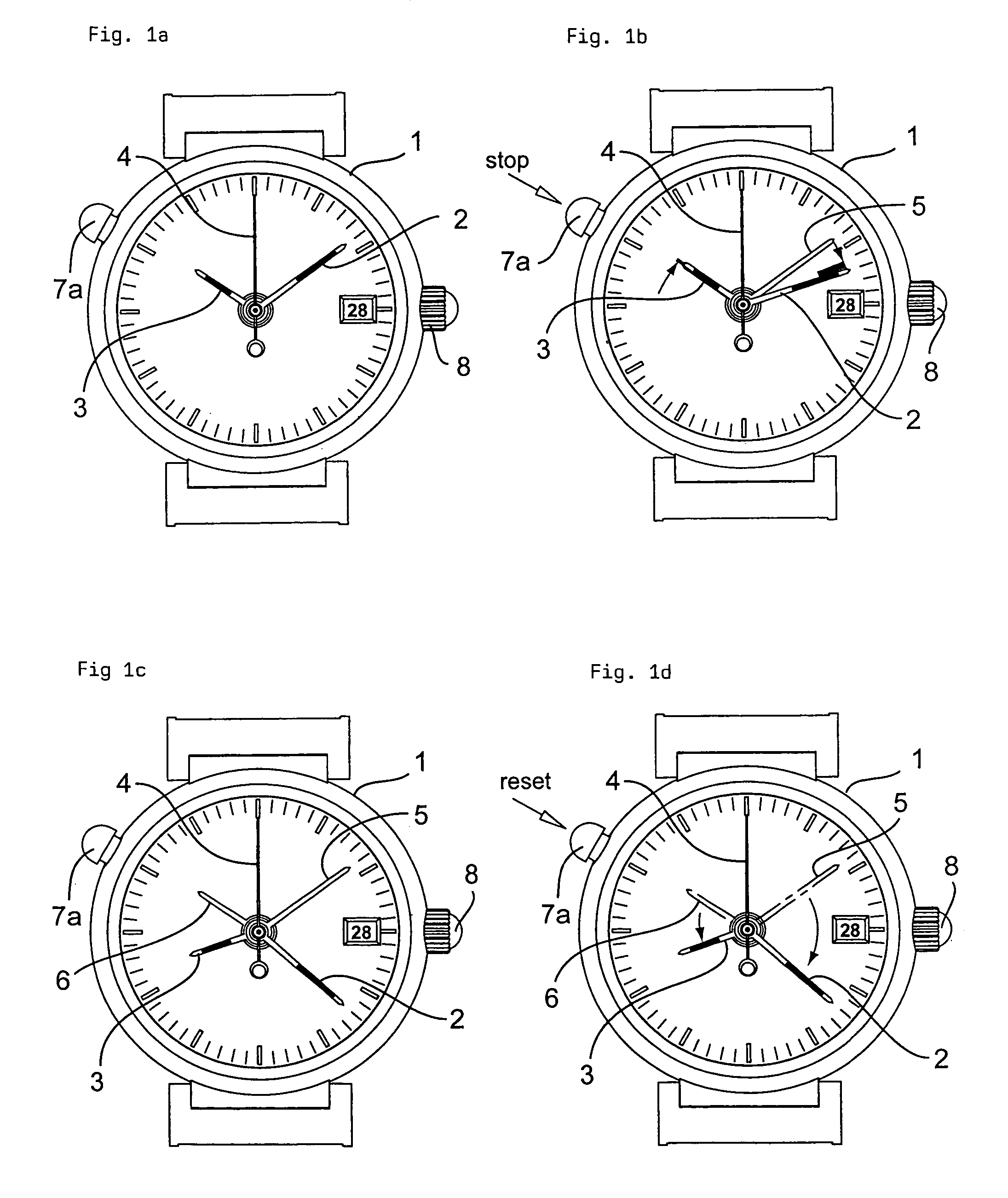
[0013]This means that this approach makes it possible to arrange the additional hand or hands in the normal mode of the watch for example under the hands of the normal time display, therefore not visible from the top, and to allow them to execute synchronous concomitant motion, while in the aforementioned known watches the additional hand or hands in contrast thereto remain in the normal mode at a stationary position.

Problems solved by technology

Thus, in many applications, the desired information must first be laboriously computed from the information of the normal time display and the measurement of the auxiliary display, and it is usually not possible to directly read the absolute time of the start or end of an event.
The use of such a manual device is obviously tedious, time-consuming and disruptive in normal reading of the time.
While this watch thus simultaneously allows normal time indication and also the measurement of the time difference, a fly back hand mechanism for moving the additional minute hand being proposed, the reading of the corresponding displays is not optimum to the extent that the additional minute hand as mentioned has only stationary positions and therefore quite adversely affects the reading process of normal time indication when its time measurement and marking function is not being used.
Namely, this hand remains in the position in which it was used last and therefore is continually visible on the dial as a disruptive element.

Method used


Image

  • Watch with fly back hand function and corresponding fly back hand mechanism
  • Watch with fly back hand function and corresponding fly back hand mechanism
  • Watch with fly back hand function and corresponding fly back hand mechanism

Examples


Embodiment Construction

[0033]The invention will be detailed below using the aforementioned figures.

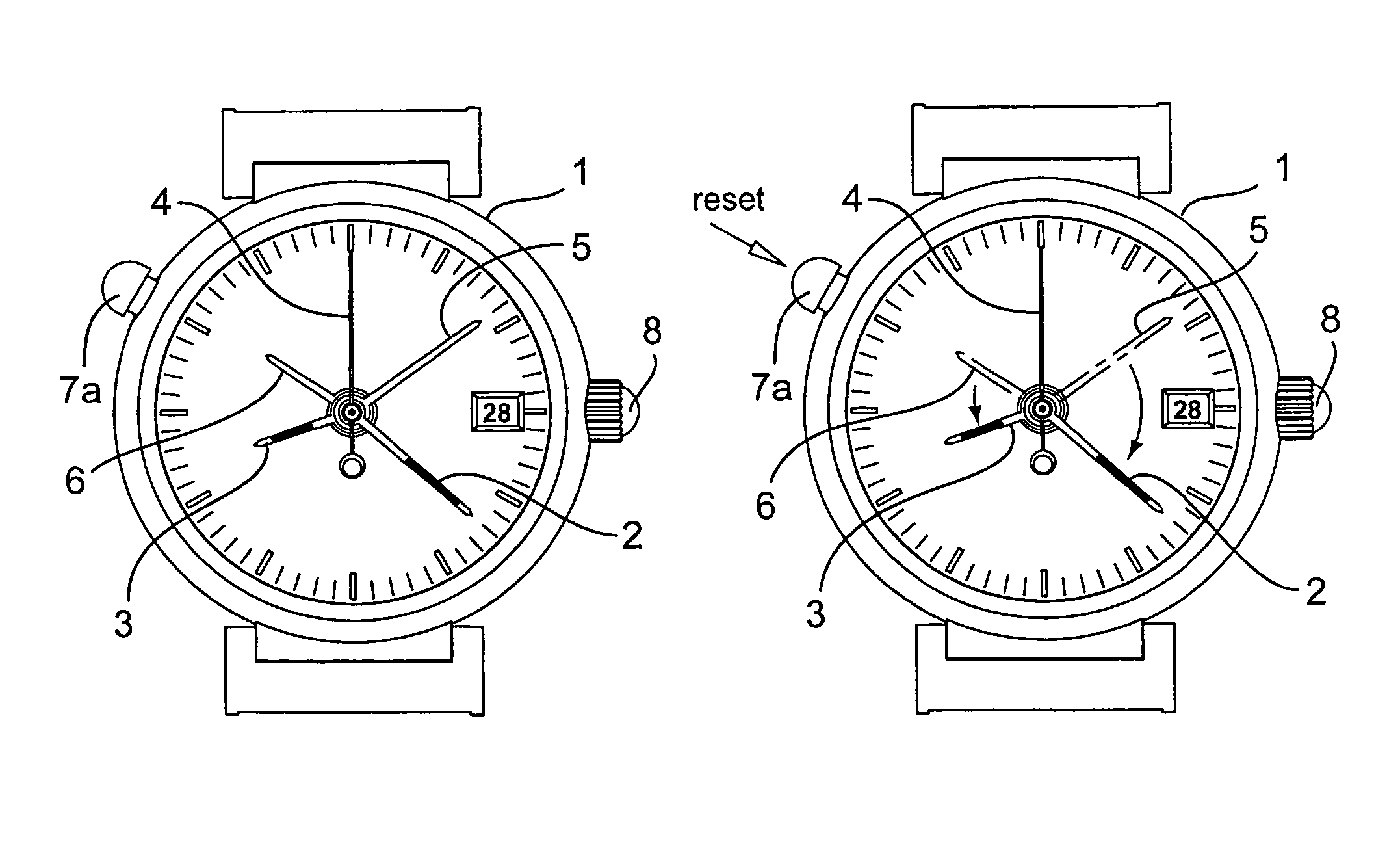
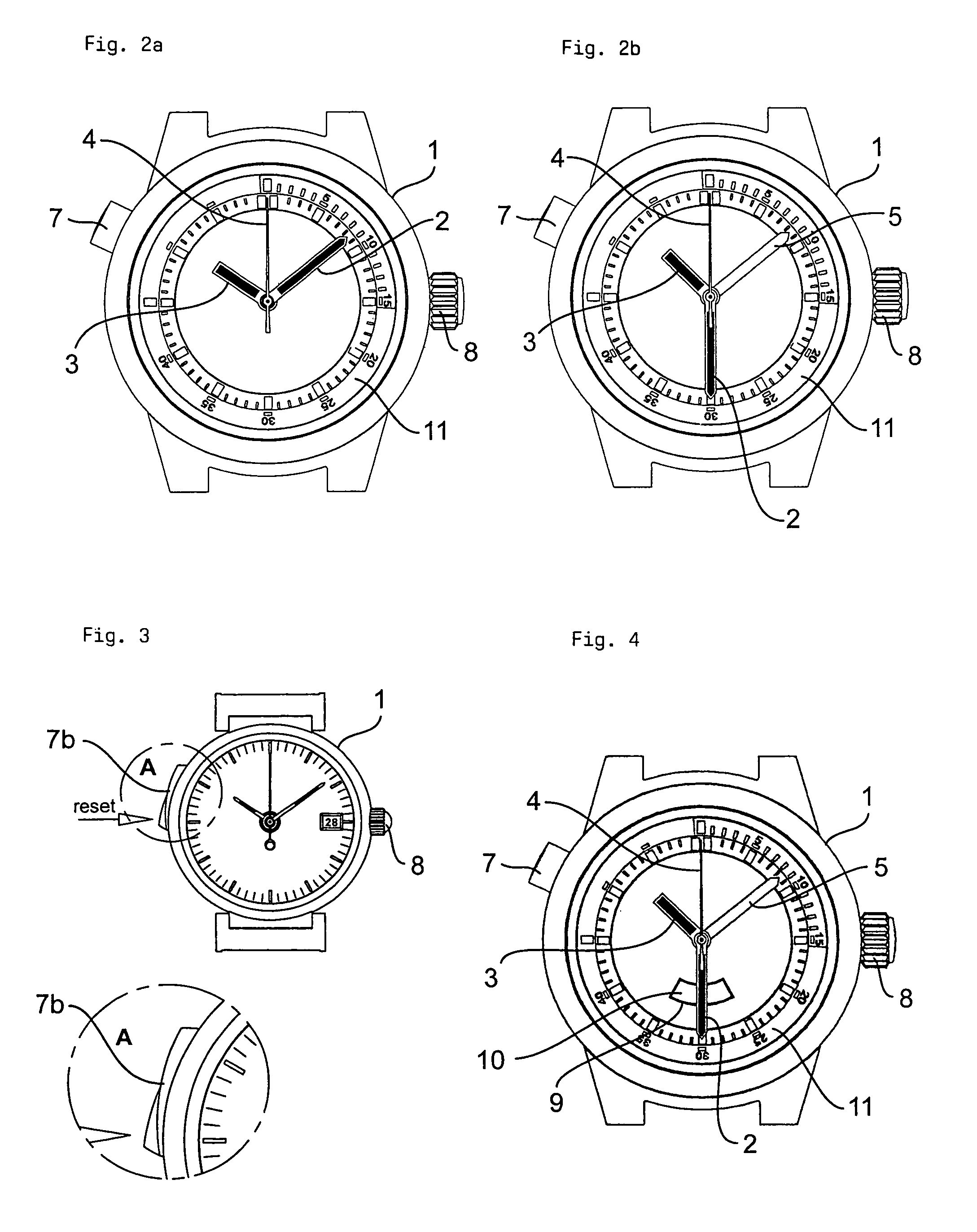
[0034]As FIG. 1 clearly shows, the present invention concerns a watch 1, especially a wristwatch, with analog time indication, which has at least one minute hand 2 and one hour hand 3. Moreover, it can have a second hand 4.

[0035]Furthermore it should be stressed that this watch has a minute and hour fly back hand mechanism or only a minute fly back hand mechanism respectively only an hour fly back hand mechanism, depending on the intended use of the watch which can relate to different orders of magnitude of the time intervals to be measured and therefore may influence the aforementioned choice.

[0036]The fly back hand mechanism has at least one fly back hand which is located coaxially to the hands 2, 3 of the normal time display, generally a minute fly back hand 5 or an hour fly back hand 6, but can also have several fly back hands, for example besides the minute fly back hand 5 an hour fly back hand 6 which ...


PUM


Abstract

A watch with an analog time display has at least one minute hand and one hour hand. This watch is moreover equipped with a fly back hand mechanism which has at least one minute fly back hand and / or hour fly back hand located coaxially to the hands of the normal time display. In the normal mode, the fly back hand or hands is / are moved synchronously with the hands of the normal time display and relative to them in an overlapping position. They can be stopped in a timer mode for marking of any instant of time and after expiry of any time interval, for again synchronously running with the hands of the normal time display. The actuated coupling of the fly back hand mechanism is located preferably non-coaxially to the axis of the motion work of the watch.

Description

FIELD OF THE INVENTION[0001]This invention relates to a watch, especially a wristwatch, with an analog time display which has at least one minute hand and one hour hand, and with a fly back hand mechanism which has at least one minute fly back hand and / or hour fly back hand located coaxially to the hands of the normal time display.[0002]Such a watch will enable both normal time indication as well as measurement of time differences or reading of the durations of various events in a simple and effective manner.BACKGROUND OF THE INVENTION[0003]The prior art in this respect includes especially chronographs which have a fly back hand function. In this case the fly back hand mechanism is generally used to temporarily stop the timer hand during the timing process, while the measurement process continues in order to allow it to then jump to the measured total time. This is for example the case in order to allow reliable reading of intermediate times while the measurement of the end time con...

Claims


Application Information

Patent Timeline
IPC IPC(8): G04F10/00G04B19/02G04B19/00G04B19/28G04F7/08
CPCG04B19/28G04F7/08G04F7/0866G04F7/0876
Inventor BRIDA, PIUSZIMMERMANN, DENISIHNEN, STEFAN
Owner RICHEMONT INT
Learn More