Force feedback applications based on cursor engagement with graphical targets

a technology of cursor engagement and feedback, applied in the field of interface devices, can solve the problems of not having physical feedback, not very intuitive feedback, and often missing the desired command by users

Inactive Publication Date: 2006-10-31
IMMERSION CORPORATION
View PDF301 Cites 146 Cited by
  • Summary
  • Abstract
  • Description
  • Claims
  • Application Information

AI Technical Summary

Benefits of technology

[0008]The present invention is directed to a force feedback implementation of a graphical environment in which force feedback click surfaces are provided. These surfaces allow a user to select buttons, icons, and other graphical objects with movement of a mouse or other user manipulable object without requiring a separate manual command gesture, such as the pressing of a button on a mouse.

Problems solved by technology

One problem with current implementation of graphical user interfaces is that two distinct actions are typically required of a user to select a function with the GUI: first, the user must accurately guide the cursor to a desired target using a mouse or other device, and second, the user must press a physical button on the mouse or other device while the cursor is displayed over the target.
Often, the user will inadvertently press the button while the cursor is not yet at the target, or after the cursor has just overshot the target, resulting in the desired function not being commanded; and the user then has to reposition the cursor and press the button again.
Or, when a desired command requires the user to guide the cursor over a target and “double-click” the physical button, the user often misses the desired command since the cursor is off the target at the time of the second “click”.
Another problem with the current target acquisition and button press commands is that there is no physical feedback to the user confirming that the selection / command process has been successfully completed.
A sound, such as a beep, may be used in some cases to confirm a completed command, but this is not very intuitive feedback.

Method used


Image

  • Force feedback applications based on cursor engagement with graphical targets
  • Force feedback applications based on cursor engagement with graphical targets
  • Force feedback applications based on cursor engagement with graphical targets

Examples


Embodiment Construction

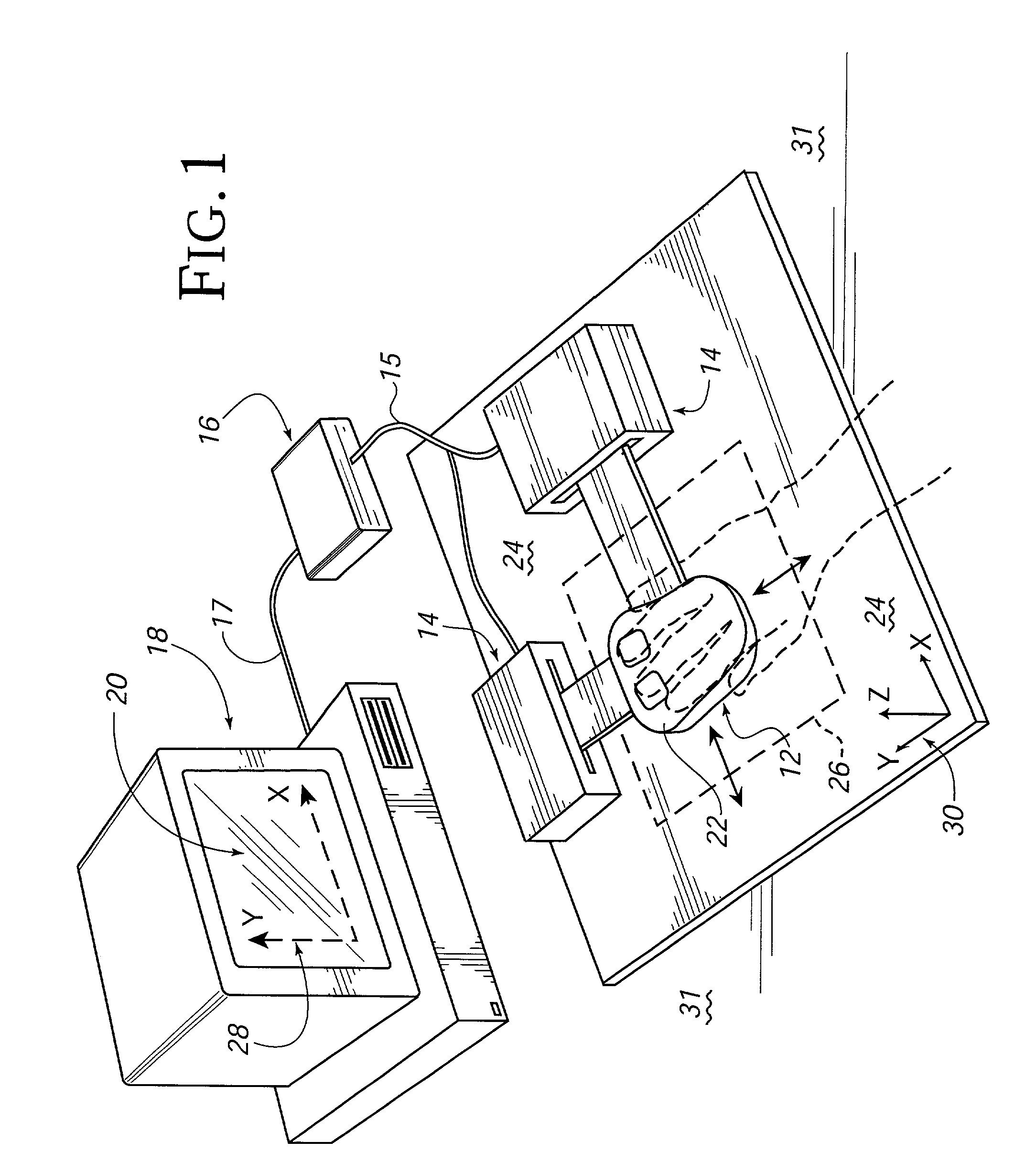
[0025]FIG. 1 is a perspective view of a force feedback interface system 10 suitable for use with the click surfaces of the present invention, capable of providing input to a host computer based on the user's manipulation of the device capable of providing force feedback to the user of the interface device based on events occurring in a program implemented by the host computer. Interface system 10 includes a user manipulable object 12, a mechanical interface 14, an electronic interface 16, and a host computer 18.

[0026]User manipulable object 12 (“user object”, “physical object”, or “manipulandum”) used in conjunction with the present invention is preferably grasped or gripped and manipulated by a user. By “grasp,” it is meant that users may releasably engage a portion of the object in some fashion, such as by hand, with their fingertips, or even orally in the case of handicapped persons. For example, images are displayed and / or modified on a display screen 20 of the computer system 1...


PUM


Abstract

A method and apparatus for providing a click surface in a graphical environment, such as a graphical user interface, implemented on a host computer for use with a force feedback interface device. A displayed cursor is controlled by a user-moveable user object, such as a mouse, of the interface device. A click surface is displayed with an associated graphical object, such as a graphical button or an edge of a window, icon, or other object. When the click surface is contacted by the cursor, a force is output opposing movement of the user object in a direction into the click surface and into the graphical object. When the user object has moved to or past a trigger position past the contact with the click surface, a command gesture signal is provided to the host computer indicating that the graphical object has been selected as if a physical input device on the user object, such as a button, has been activated by the user. Preferably, the host computer displays the graphical environment including the click surface and cursor, while a microprocessor local to the interface device controls the force output of the click surface in parallel with the host display.

Description

CROSS REFERENCE TO RELATED APPLICATIONS[0001]This application is a continuation of U.S. patent application Ser. No. 09 / 590,856, filed Jun. 8, 2000, now U.S. Pat. No. 6,317,116, which is a continuation of application Ser. No. 08 / 879,296, filed Jun. 18, 1997, now U.S. Pat. Ser. No. 6,078,308, which is a continuation-in-part of application Ser. No. 08 / 571,606, filed Dec. 13, 1995, now U.S. Pat. No. 6,219,032, and application Ser. No. 08 / 756,745, filed Nov. 26, 1996, now U.S. Pat. No. 5,825,308, all of which are assigned to the assignee of this present application, and all of which are incorporated by reference herein in their entireties.BACKGROUND OF THE INVENTION[0002]The present invention relates generally to interface devices for allowing humans to interface with computer systems, and more particularly to computer interface devices that allow the user to provide input to graphical environments on computer systems and provide force feedback to the user.[0003]Computer systems are used...

Claims


Application Information

Patent Timeline
Patent Type & Authority Patents(United States)
IPC IPC(8): G09G5/00G05G9/047G06F3/00G06F3/01G06F3/033G06F3/048H04L29/06
CPCG05G9/047G06F3/011G06F3/016G06F3/0354G06F3/03543G06F3/03548G06F3/04812G06F3/0482G06F3/04842A63F2300/1025A63F2300/1037G05G2009/0477G06F2203/014H01H2003/008H04L67/38H04L67/131
Inventor ROSENBERG, LOUIS B.CHANG, DEAN C.
Owner IMMERSION CORPORATION
Why Eureka
Try Eureka