Impact driver having a percussion application mechanism which operation mode can be selectively switched between percussion and non-percussion modes

a technology of impact driver and operation mode, which is applied in the direction of percussive tools, manufacturing tools, portable drilling machines, etc., can solve the problems of reducing usability and exchange of tools, and achieve the effect of improving operability and reducing costs

Inactive Publication Date: 2006-11-07
MAKITA CORP
View PDF9 Cites 71 Cited by
  • Summary
  • Abstract
  • Description
  • Claims
  • Application Information

AI Technical Summary

Benefits of technology

[0007]In order to solve this problem, an object in accordance with a first aspect of the present invention is to provide an impact driver capable of boring by percussion easily and providing an excellent usability.
[0011]In a fourth aspect of the present invention based on the first aspect, with the impact driver having a chuck sleeve for attaching or detaching a tool at the top of the output shaft by sliding operation in the axial direction, in order to simply form the percussion application mechanism, the percussion application mechanism comprises a first cam externally provided at the output shaft for rotating separately from the output shaft and on which a part of the chuck sleeve mounts externally, a second cam inserted into the output shaft with play at the rear of the first cam and fixed to the side of the housing, cam gears formed on the first and second cams at opposing faces thereof for contacting each other at the backward position of the output shaft, and a regulating means provided between the chuck sleeve and the output shaft and capable of arbitrarily regulating the rotation of the first cam by means of the rotative operation of the chuck sleeve.
[0013]According to the first aspect of the present invention, as a percussion mode can be selected by the percussion application mechanism, both boring and screwing can be conducted with an impact driver only, whereby improvement of its operability can be expected.
[0015]According to the third aspect of the present invention, in addition to the effect of the second aspect, the regulating means can be simply formed at the front edge of the housing where handling is easy.
[0016]According to the fourth aspect of the present invention, in addition to the effect of the first aspect, the chuck sleeve is used as an operating member for changing modes, which is a part of the regulating means. Consequently, an impact driver of the present invention can be obtained from a conventional one with only a slight model change, having a great advantage that the percussion application mechanism can be formed with a reduced cost.
[0017]According to the fifth aspect of the present invention, in addition to the effect of the fourth aspect, the regulating means can be simply formed at the front edge of the output shaft where handling is easy.

Problems solved by technology

Consequently, it is troublesome to exchange tools and therefore usability might be reduced.

Method used


Image

  • Impact driver having a percussion application mechanism which operation mode can be selectively switched between percussion and non-percussion modes
  • Impact driver having a percussion application mechanism which operation mode can be selectively switched between percussion and non-percussion modes
  • Impact driver having a percussion application mechanism which operation mode can be selectively switched between percussion and non-percussion modes

Examples


embodiment 1

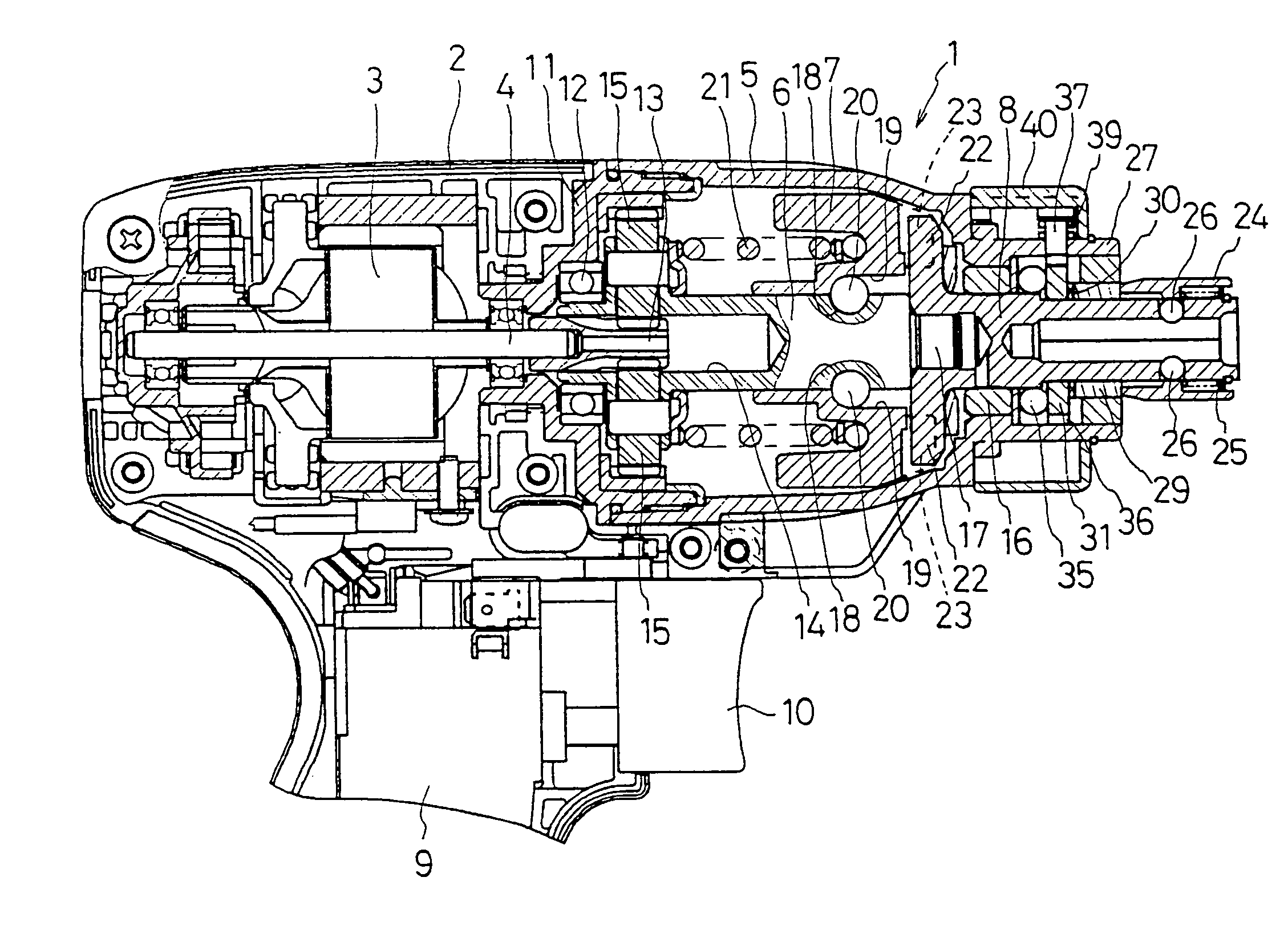
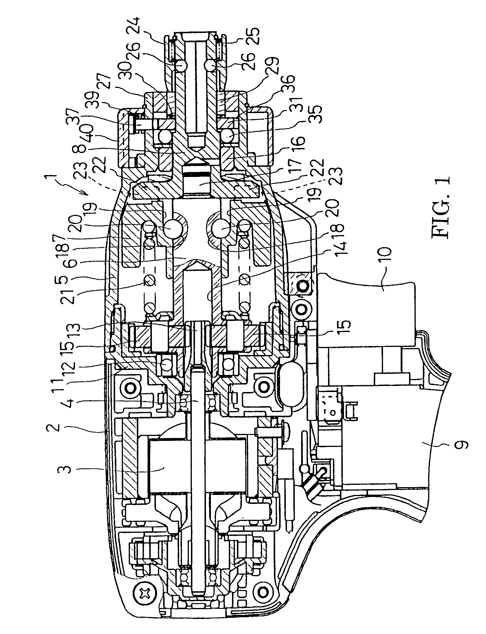
[0033]In the impact driver 1 in accordance with the embodiment 1, the anvil 8 is provided so as to be slightly movable in the axial direction. Moreover, the percussion application mechanism, where the percussion to the anvil 8 occurs in accordance with the rotation of the anvil 8, is optionally provided. Because of this, both boring and screwing can be conducted only with the impact driver, whereby improvement of its operability can be expected.

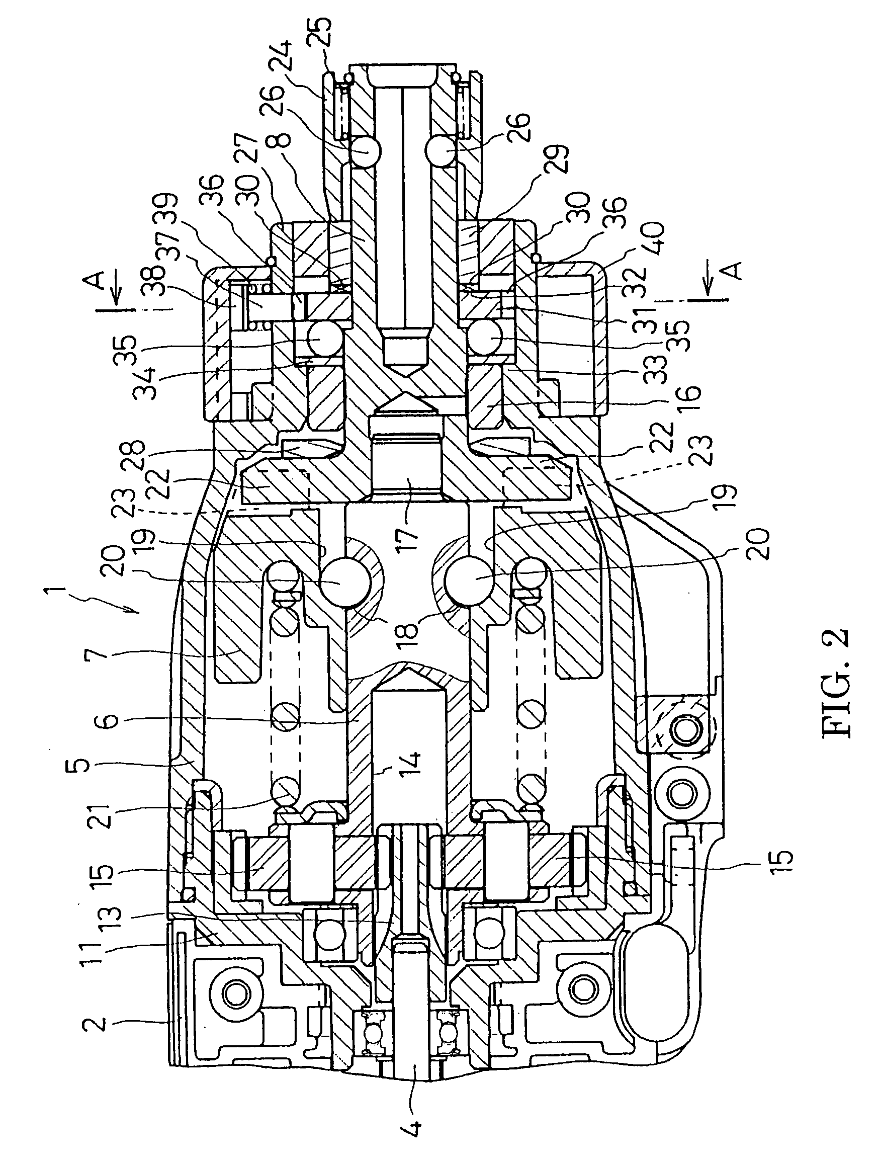
[0034]In particular, the percussion application mechanism comprises a first cam 29 externally provided at the anvil 8 for rotating integrally with the same, a second cam 31 inserted into the anvil 8 with play at the rear of the first cam 29 to be regulated its moving in the axial direction, cam gears 30, 32 formed on the first and second cams 29, 31 at opposing faces thereof for contacting with each other at the backward position of the anvil 8, and a regulating means provided in the cylindrical portion 27 of the hammer case 5 so as to regula...

first embodiment

[0039]Next, another embodiment of an impact driver will be explained. It should be noted that the same components as those in the first embodiment are assigned the same reference numbers and explanation thereof is omitted.

[0040]In an impact driver 1 as shown in FIG. 5, the anvil 8 has a cylindrical first cam 50 and a second cam 52 which are externally provided from the front respectively. The rear portion of the first cam 50 is axially supported by a cylindrical portion 27 of a hammer case 5, whereby the first cam 50 can move separately from the anvil 8 in the rotating and axial direction. Cam gears 51, 51 . . . are provided at the rear of the first cam 50 in the radial direction. The second cam 52 is pressed into the cylindrical portion 27 from backward to be integral with the hammer case 5. Moreover, the second cam 52 axially supports the anvil 8 and regulates a forward position of the anvil 8 by a flange portion 53 formed at the rear end thereof.

[0041]According to this configurat...

second embodiment

[0046]Also in the impact driver 1 of the second embodiment, as the percussion application mechanism is optionally provided, both boring and screwing can be conducted with one impact driver only, so that improvement of operability can be expected.

[0047]In particular, the percussion application mechanism comprises a first cam 50 being externally provided at the anvil 8 for rotating separately from the anvil 8 and on which a part of the chuck sleeve 24 mounts externally, a second cam 52 inserted into the anvil 8 with play at rear of the first cam 50 and fixed to the side of the hammer case 5, cam gears 51, 54 formed on the first and second cams 50, 52 at opposing faces thereof for contacting each other at the backward position of the anvil 8, and a regulating means provided between the chuck sleeve 24 and the anvil 8 and capable of arbitrarily regulating the rotation of the first cam 50 by means of the rotative operation of the chuck sleeve 24. In other words, the chuck sleeve 24 for a...


PUM

PropertyMeasurementUnit
torqueaaaaaaaaaa
rotationaaaaaaaaaa
circumferenceaaaaaaaaaa

Abstract

An impact driver capable of boring and having an excellent usability is provided. An anvil(8) is arranged so as to slightly move in the axial direction. A first cam(29) having cam gears(30, 30 . . . ) is externally provided at the anvil so as to be integral with the anvil(8). At the rear of the first cam(29), a second cam(31) having cam gears(32, 32 . . . ) and further having cam gears(36, 36 . . . ) at its outer circumference is externally provided to the anvil(8) so as to be rotatable. At the backward position of the anvil(8), the cam gears(30, 32) contacts with each other. On the other hand, in the cylindrical portion(27) of the hammer case(5), an engaging pin(37) capable of engaging with an engaging gear(36) of the second cam(31) is provided. The engaging pin(37) can change its location by the rotative operation of a mode-change ring(40), whereby a percussion mode and a non-percussion mode is selected.

Description

BACKGROUND OF THE INVENTION[0001]This application claims the benefit of Japanese Patent Application No. 2004-34016 filed Feb. 10, 2004, the entirety of which is incorporated by reference.[0002]1. Field of the Invention[0003]The present invention relates to an impact driver capable of applying rotation and the intermittent impact operation to an output shaft.[0004]2. Description of the Related Art[0005]An impact driver includes a rotation impact mechanism provided between a motor housed in a housing and an output shaft protruding from the housing so as to transfer a motor torque to the output shaft as well as apply the impact operation to the same in the rotative direction in accordance with increase of a load on the output shaft. For example, Japan Published Unexamined Patent Application No. 2002-273666 discloses a rotation impact mechanism in which a spindle rotated by a motor is connected to a hammer through cam grooves and balls, and an anvil (an output shaft) attachable to and d...

Claims


Application Information

Patent Timeline
Patent Type & Authority Patents(United States)
IPC IPC(8): B25B23/159B23B45/16B25B21/02B25D11/10B25D16/00
CPCB25B21/00B25B21/02B25B21/023B25D11/102B25D16/006B25D2216/0023B25D2216/0038
Inventor FURUTA, TAKEFUMINAGASAKA, HIDENORI
Owner MAKITA CORP
Why Eureka
Try Eureka