Impact driver

Inactive Publication Date: 2005-08-11
MAKITA CORP
View PDF7 Cites 42 Cited by
  • Summary
  • Abstract
  • Description
  • Claims
  • Application Information

AI Technical Summary

Benefits of technology

[0014] According to the second aspect of the present invention, in addition to the effect of the first aspect, the percussion application mechanism can be simply formed.
[0015] According to the third aspect of the present invention, in addition to the effect of the second aspect, the regulating means can be simply formed at the front edge of the housing where handling is easy.
[0016] According to the fourth aspect of the present invention, in addition to the effect of the first aspect, the chuck sleeve is used as an o

Problems solved by technology

Consequently, it is troublesome to exchange t

Method used


Image

  • Impact driver
  • Impact driver
  • Impact driver

Examples


Example

First Embodiment

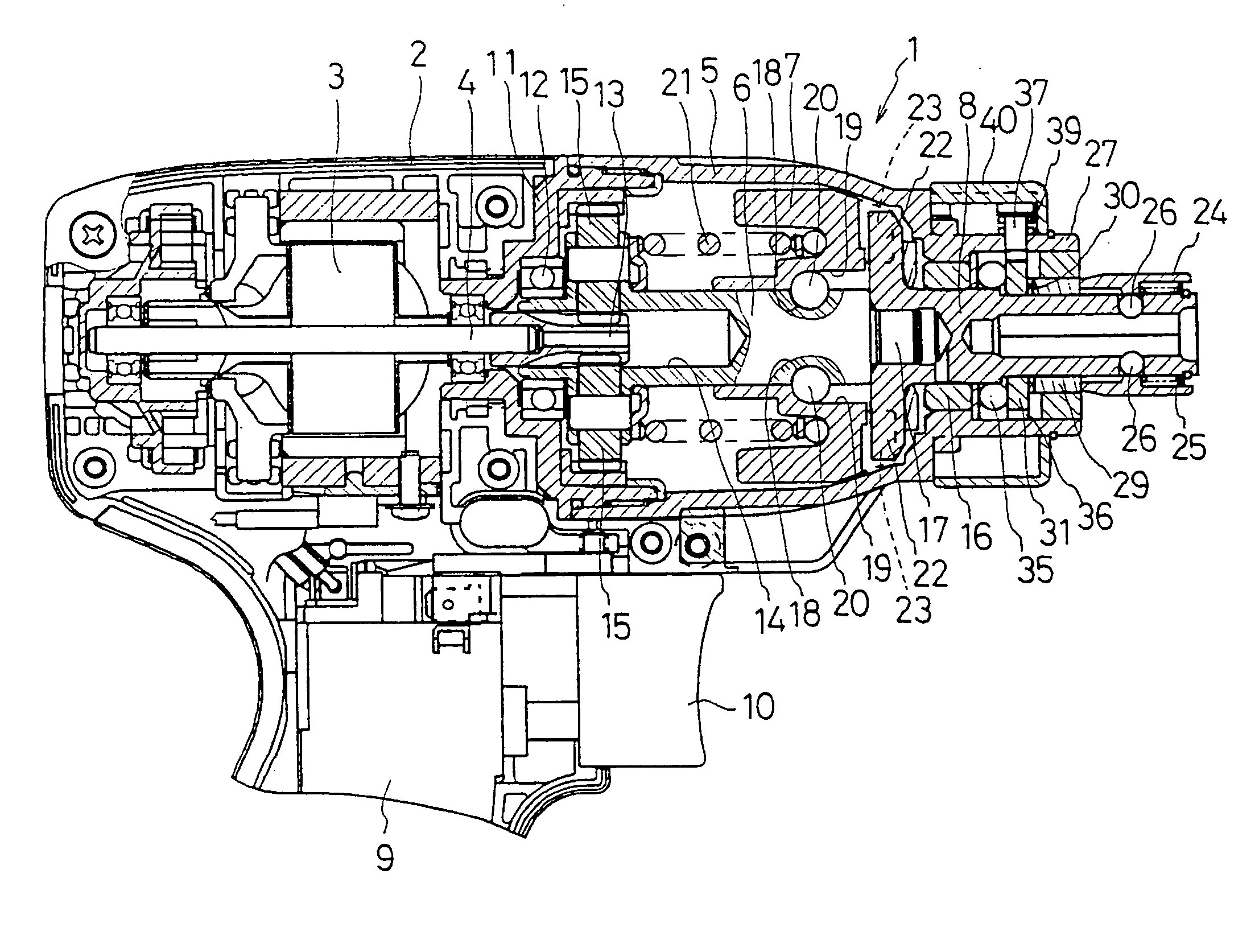
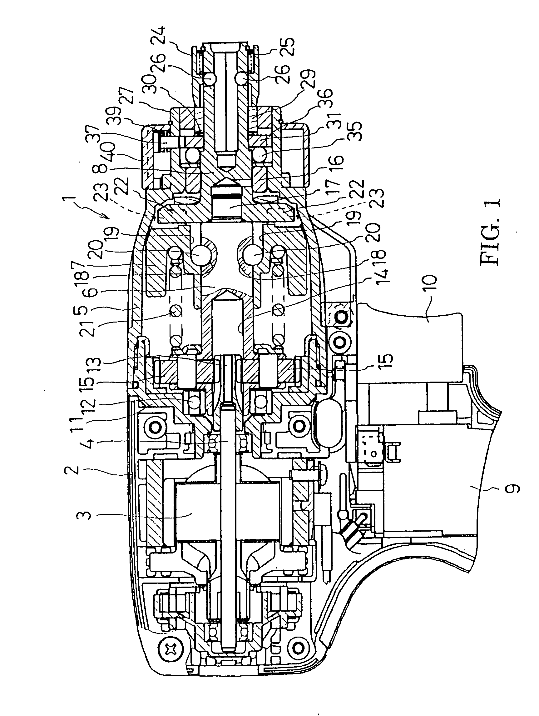
[0026]FIG. 1 is a partial vertical section view showing an example of an impact driver. An impact driver 1 has a motor 3 accommodated in a body housing 2. At the front of the body housing 2, a hammer case 5 accommodating a spindle 6 and a hammer 7 is mounted as a front housing. An anvil 8 serving as an output shaft protrudes at the front of the hammer case 5. The reference number 9 denotes a switch and the reference number 10 denotes a trigger. Between the body housing 2 and the hammer case 5, a gear housing 11 is provided which axially supports a motor shaft 4 of the motor 3 so as to allow the motor shaft 4 to protrude into the hammer case 5. Moreover, the gear housing 11 axially supports the end of the spindle 6 through a ball bearing 12. A pinion 13 is mounted at the top of the motor shaft 4 which inserts coaxially with play into a hollow portion 14 formed at the end of the spindle 6. In accordance with this structure, the motor shaft 4 engages with a plurality o...

Example

Second Embodiment

[0039] Next, another embodiment of an impact driver will be explained. It should be noted that the same components as those in the first embodiment are assigned the same reference numbers and explanation thereof is omitted.

[0040] In an impact driver 1 as shown in FIG. 5, the anvil 8 has a cylindrical first cam 50 and a second cam 52 which are externally provided from the front respectively. The rear portion of the first cam 50 is axially supported by a cylindrical portion 27 of a hammer case 5, whereby the first cam 50 can move separately from the anvil 8 in the rotating and axial direction. Cam gears 51, 51 . . . are provided at the rear of the first cam 50 in the radial direction. The second cam 52 is pressed into the cylindrical portion 27 from backward to be integral with the hammer case 5. Moreover, the second cam 52 axially supports the anvil 8 and regulates a forward position of the anvil 8 by a flange portion 53 formed at the rear end thereof.

[0041] Accor...


PUM

PropertyMeasurementUnit
Circumferenceaaaaaaaaaa

Abstract

An impact driver capable of boring and having an excellent usability is provided. An anvil(8) is arranged so as to slightly move in the axial direction. A first cam(29) having cam gears(30, 30 . . . ) is externally provided at the anvil so as to be integral with the anvil(8). At the rear of the first cam(29), a second cam(31) having cam gears(32, 32 . . . ) and further having cam gears(36, 36 . . . ) at its outer circumference is externally provided to the anvil(8) so as to be rotatable. At the backward position of the anvil(8), the cam gears(30, 32) contacts with each other. On the other hand, in the cylindrical portion(27) of the hammer case(5), an engaging pin(37) capable of engaging with an engaging gear(36) of the second cam(31) is provided. The engaging pin(37) can change its location by the rotative operation of a mode-change ring(40), whereby a percussion mode and a non-percussion mode is selected.

Description

BACKGROUND OF THE INVENTION [0001] This application claims the benefit of Japanese Patent Application Number 2004-34016 filed Feb. 10, 2004, the entirety of which is incorporated by reference. [0002] 1. Field of the Invention [0003] The present invention relates to an impact driver capable of applying rotation and the intermittent impact operation to an output shaft. [0004] 2. Description of the Related Art [0005] An impact driver includes a rotation impact mechanism provided between a motor housed in a housing and an output shaft protruding from the housing so as to transfer a motor torque to the output shaft as well as apply the impact operation to the same in the rotative direction in accordance with increase of a load on the output shaft. For example, Japan Published Unexamined Patent Application No. 2002-273666 discloses a rotation impact mechanism in which a spindle rotated by a motor is connected to a hammer through cam grooves and balls, and an anvil (an output shaft) attach...

Claims


Application Information

Patent Timeline
IPC IPC(8): B23B45/16B25B21/02B25D11/10B25D16/00
CPCB25B21/00B25B21/02B25B21/023B25D2216/0038B25D16/006B25D2216/0023B25D11/102
Inventor FURUTA, TAKEFUMINAGASAKA, HIDENORI
Owner MAKITA CORP
Why Eureka
Try Eureka