Airbag with a strategically placed recess

a technology of airbags and recesses, which is applied in the direction of pedestrian/occupant safety arrangements, vehicle components, vehicular safety arrangments, etc., can solve the problems of high reliability, high cost, and high cost of sensors, and achieve the effect of high reliability and no significant cost penalty

Active Publication Date: 2006-11-07
KEY SAFETY SYST
View PDF24 Cites 80 Cited by
  • Summary
  • Abstract
  • Description
  • Claims
  • Application Information

AI Technical Summary

Benefits of technology

[0012]An airbag according to the present invention can provide these performance capabilities with a standard inflator.
[0013]An airbag system according to the present invention can perform without requiri...

Problems solved by technology

The use of such conventional passenger side airbags is known to create a risk of injury of small children and infants as well as out of position vehicle occupants.
These sensors are costly and very sophisticated and require a very high degree of reliability to insure they function over the life of a vehicle.
To date none of the systems commonly used can accommodate the deployment of an airbag towards an infant in an infant seat facing the rear of a vehicle in the front seat of a vehicle.
These a...

Method used


Image

  • Airbag with a strategically placed recess
  • Airbag with a strategically placed recess
  • Airbag with a strategically placed recess

Examples


Embodiment Construction

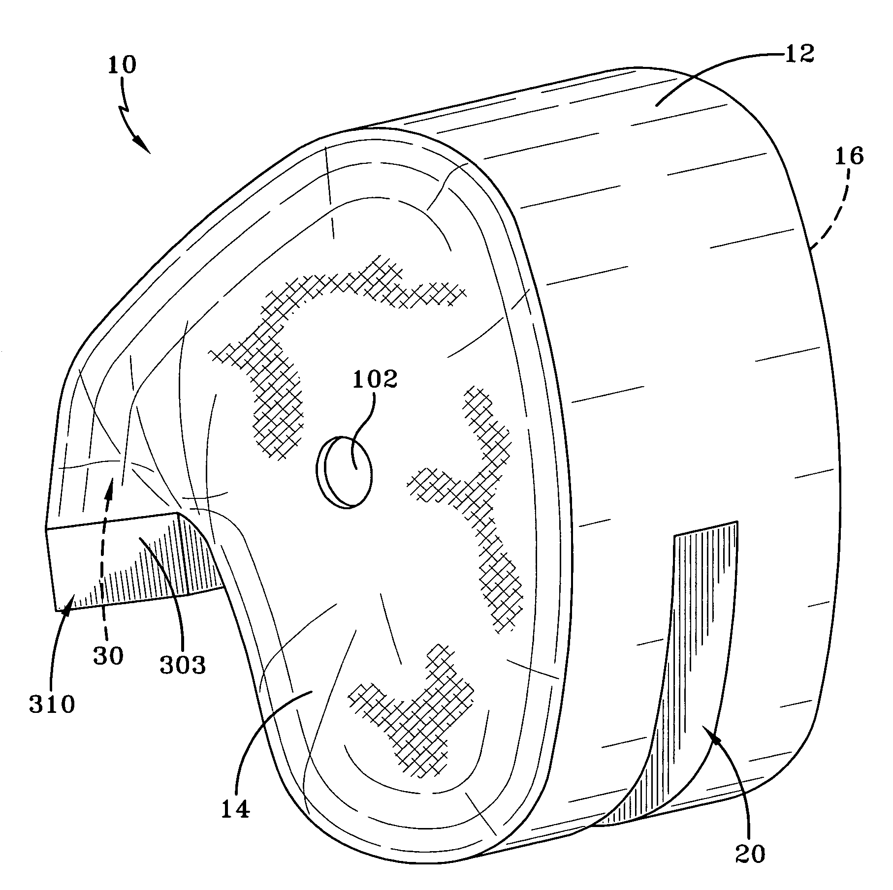
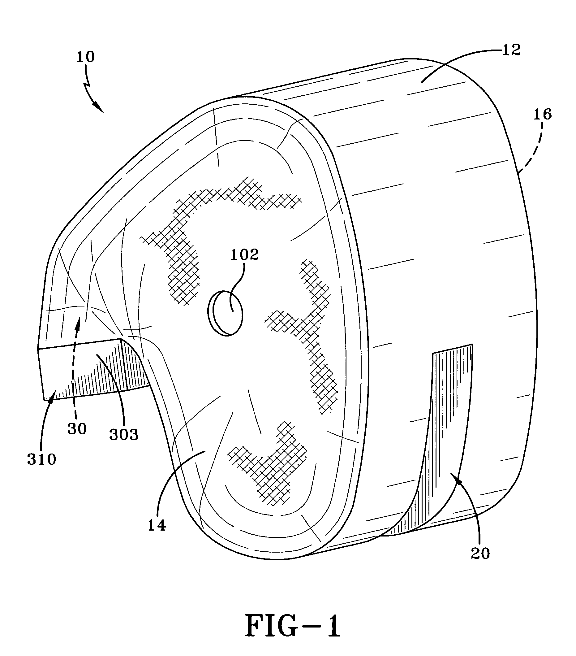
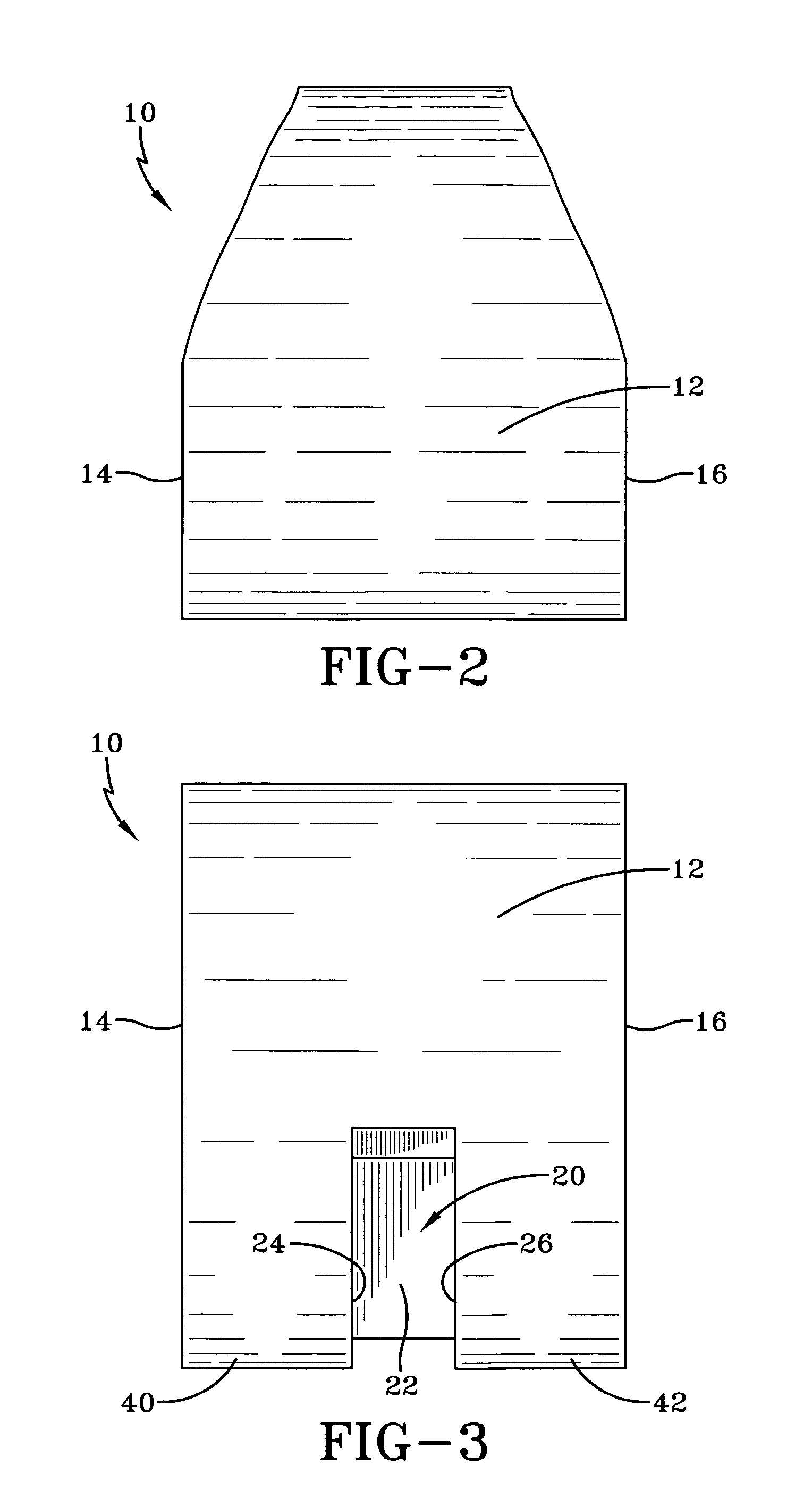
[0033]With reference to FIGS. 1 through 5H the present invention according to a preferred embodiment is illustrated. Shown in FIG. 1 is an airbag 10 that has a main panel 12 and two side panels 14, 16. The main panel 12 has a top portion, a front portion and a bottom portion and as shown in FIG. 5A can be made from a single panel of airbag fabric. The combination of the main panel 12 and side panels 14, 16 define a single inflatable chamber 301. The inflatable chamber 301 has an opening formed by the ends of the main panel cooperating with the side panels to create a passageway 30 that allows inflation gas to enter the inflatable chamber 301 and inflate the airbag 10. With further reference to FIG. 1 a recessed portion 20 of the airbag is shown. The recessed portion 20 illustrated in FIG. 3 has a center recess panel 22, a left recess panel 24 and a right recess panel 26, the combination of which forms a recessed portion 20 within the main panel 12. The term “recess” as used herein m...


PUM


Abstract

An airbag (10) has an inflatable chamber (301) defined by a main front panel (12) and a pair of side panels (24), (26). The airbag (10) has a vertically oriented recessed portion (20) on the main panel (12) located on a lower portion of an airbag (10), preferably vertically at or below a gas inlet passageway (30). The recessed portion (20) divides the airbag (10) into two lower lobe portions (40, 42) on each side of the recessed portion (20). Upon inflation an internal tether (50) is attached to the recessed portion (20) and is anchored at or adjacent to the gas inlet passageway (30) thereby limiting forward movement of the recessed portion (20) upon inflation. The airbag (10) is useful as a frontal airbag, particularly a passenger frontal airbag.

Description

RELATED APPLICATIONS[0001]This application is a Continuation in Part of U.S. patent application Ser. No. 11 / 252,426 filed on 17 Oct. 2005 entitled “Grooved Air Bag”.FIELD OF THE INVENTION[0002]This invention relates to passenger side airbags deployed from an instrument panel of a vehicle.BACKGROUND OF THE INVENTION[0003]As shown in prior art FIG. 13, a conventional passenger side airbag 200 is inflated by an airbag inflator 280. The airbag 200 typically has a single inflatable chamber 330 inflated by gas from the inflator 280. The face portion or front panel 320 of the airbag 200 impacts the vehicle occupant 220 along the chest, shoulders and head. As the vehicle occupant's seated position at the time of airbag deployment deviates from the normal seated position by taking a position closer to the vehicle's instrument panel relative to the seat back 260 of the seat 240, the velocity at which the airbag impacts the vehicle occupant increases. If the vehicle occupant's body is on or ne...

Claims


Application Information

Patent Timeline
IPC IPC(8): B60R21/16B60R21/233B60R21/2338
CPCB60R21/233B60R21/2338B60R21/231B60R2021/0004B60R2021/0044B60R2021/23382B60R2021/23386B60R21/205
Inventor PANG, HYUNSOKSHKOUKANI, MUTAZKIM, SOONSIKYANG, JAE-SUNGHARIHARAN, PREMPADIYAR, PRABHAKARJUNG, JIN HOSADENWATER, ROBERTJU, CHANG
Owner KEY SAFETY SYST
Why Eureka
Try Eureka