Computer enclosure incorporating bezel pivoting mechanism

Inactive Publication Date: 2006-11-07
HON HAI PRECISION IND CO LTD
View PDF3 Cites 22 Cited by
  • Summary
  • Abstract
  • Description
  • Claims
  • Application Information

AI Technical Summary

Benefits of technology

[0005]Accordingly, an object of the present invention is to provide a computer enclosure incorpo

Problems solved by technology

It is inconvenient for a user to attach and remove the bezel by manipulating the screws.
Furthermore, in assembly of such computer enclosure on a factory pr

Method used


Image

  • Computer enclosure incorporating bezel pivoting mechanism
  • Computer enclosure incorporating bezel pivoting mechanism
  • Computer enclosure incorporating bezel pivoting mechanism

Examples


Example

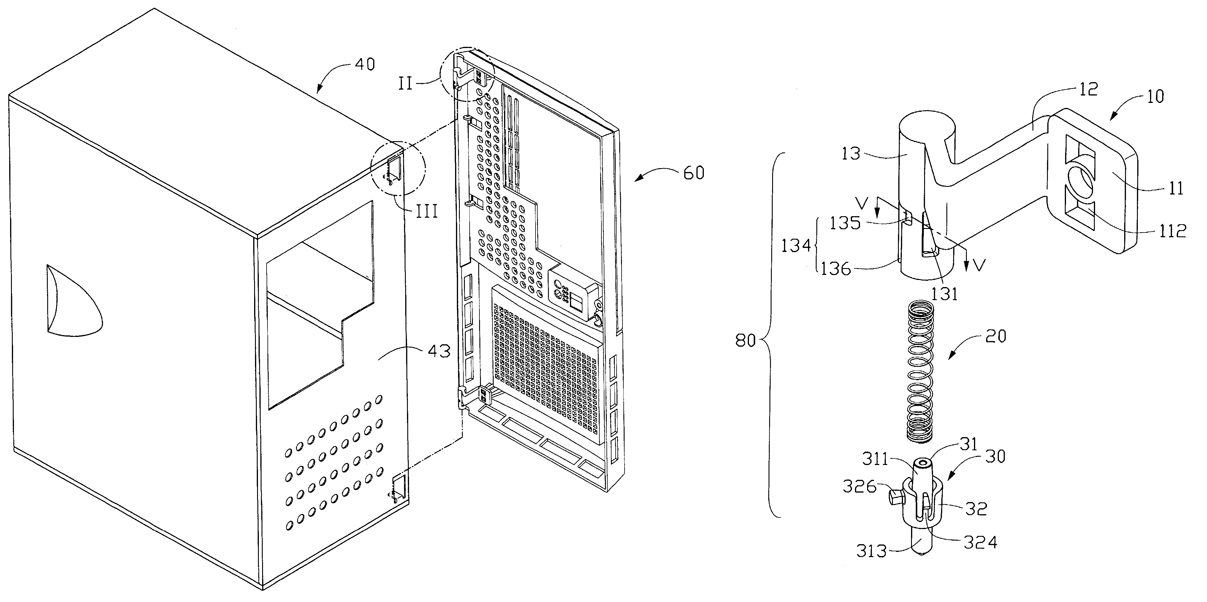
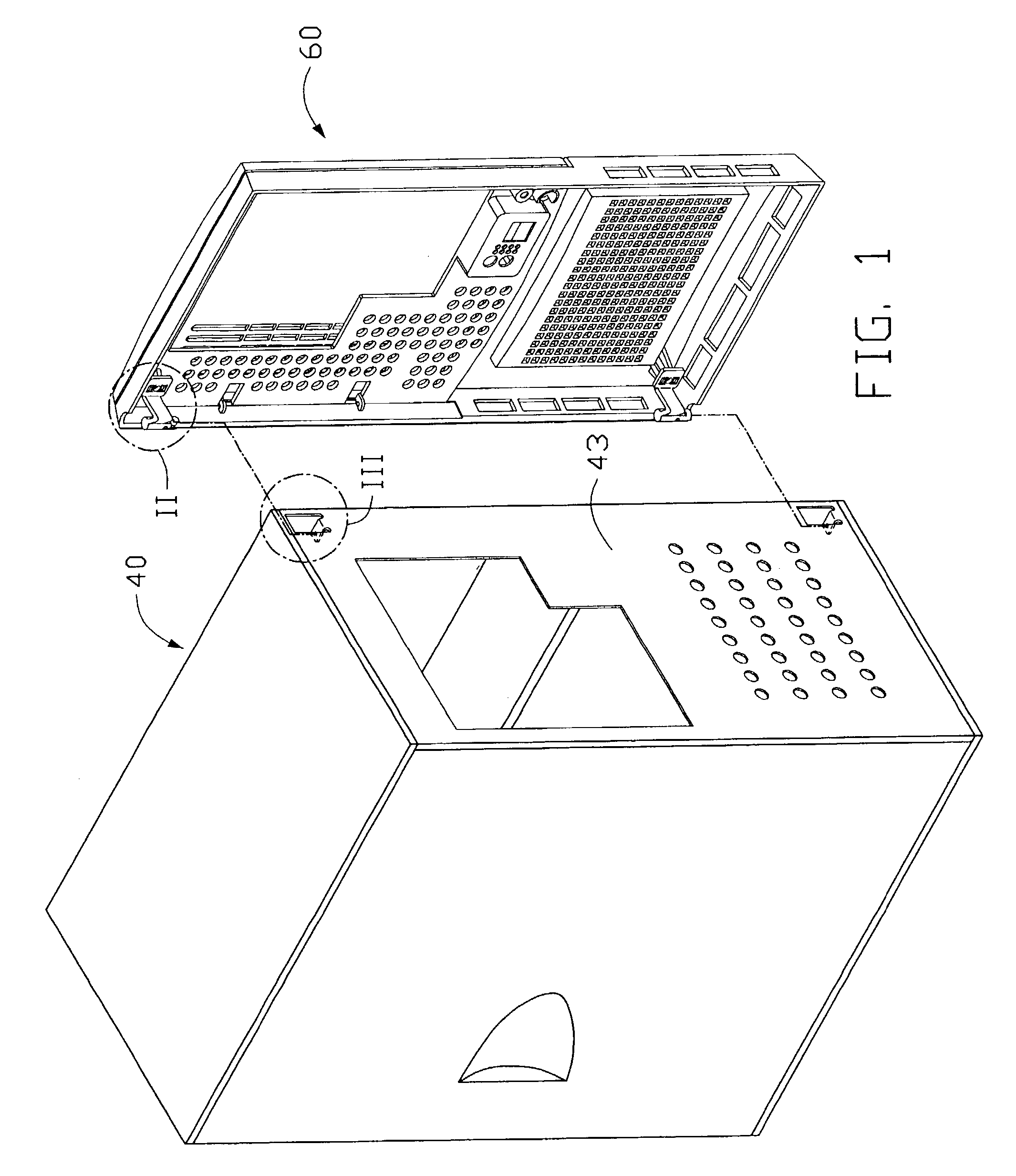
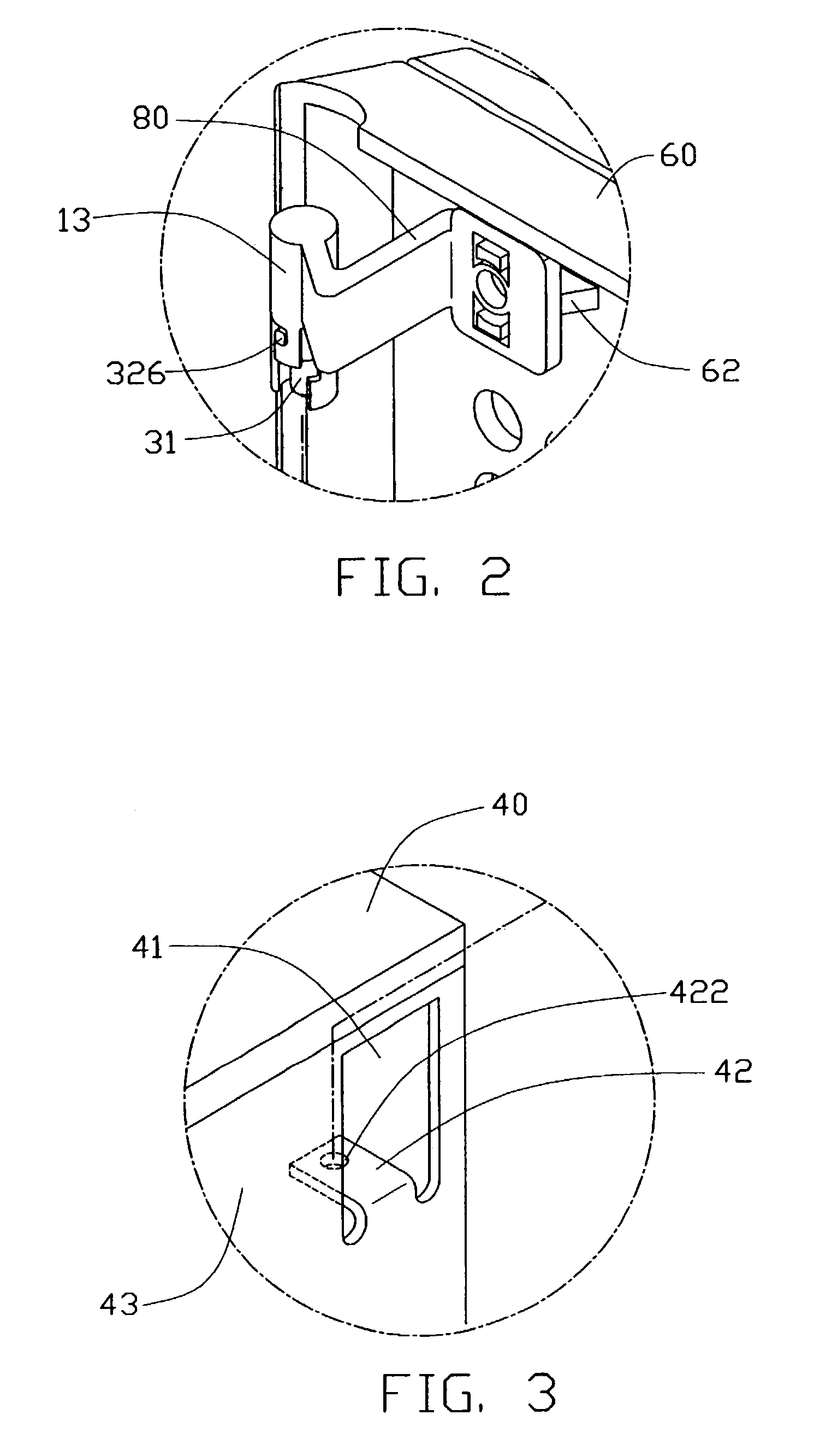
[0014]Referring to FIGS. 1 through 3, a computer enclosure in accordance with a preferred embodiment of the present invention comprises a cage 40 and a bezel 60. A pair of pivot devices 80 pivotably attaches the bezel 60 to the cage 40. A pair of vertically spaced bent plates 42 is bent inwardly from one side of a front panel 43 of the cage 40. A pair of openings 41 is thus defined in the front panel 43. A through hole 422 is defined in each bent plate 42. A pair of vertically spaced fixing pedestals 62 is formed at one side of an inside face of the bezel 60, generally corresponding in position to the openings 41 of the front panel 43.

[0015]Referring also to FIGS. 4 through 6, each pivot device 80 comprises a base portion 10, a coil spring 20 and a pivot 30. The base portion 10 comprises a fixing part 11, a hollow cylinder 13, and a connecting arm 12 integrally interconnecting the fixing part 11 and the cylinder 13. A pair of holes 112 is defined in the fixing part 11, for fixedly r...


PUM


Abstract

A computer enclosure includes a cage (40), a bezel (60), and two pivot devices (80). The cage has a front panel (43) defining two holes (422). Each pivot device (80) is fixed to the bezel, and includes a cylinder (13), a spring (20) and a pivot (30). The cylinder receives the spring therein. Two L-shaped apertures (131) are defined in opposite sides of the cylinder. Each pivot includes a central pin (31), and a circumferential wall (32) surrounding most of the pin. Two resilient L-shaped hooks (324) are formed at opposite sides of the circumferential wall. The spring is compressed between a top end of the cylinder and the circumferential wall. When the hooks are slid from horizontal portions (132) of the apertures to vertical portions (133) of the apertures, the spring pushes the pivot downwardly, and the pin is pivotably engaged in a corresponding hole of the front panel.

Description

BACKGROUND OF THE INVENTION[0001]1. Field of the Invention[0002]The present invention relates to computer enclosures, and more particularly to a mechanism for attaching a bezel to a computer enclosure.[0003]2. Description of the Related Art[0004]A conventional computer enclosure comprises a cage and a bezel. The bezel is attached to the cage with screws. It is inconvenient for a user to attach and remove the bezel by manipulating the screws. Furthermore, in assembly of such computer enclosure on a factory production line, manual insertion and removal of screws is slow, laborious and inefficient. To address the above problems, Taiwan Patent No. 506565 discloses a computer enclosure that incorporates a pivoting mechanism connecting a bezel with a cage of the computer enclosure. A pair of screws is provided to pivotably secure the bezel to the cage. The bezel is rotated about the screws. However, this computer enclosure still requires the use of screws.SUMMARY OF THE INVENTION[0005]Acc...

Claims


Application Information

Patent Timeline
IPC IPC(8): A47B97/00E05D7/10G06F1/18
CPCG06F1/181E05D7/1005E05D7/1011E05D7/1016E05D7/1022E05Y2900/606
Inventor CHEN, LI PING
Owner HON HAI PRECISION IND CO LTD
Why Eureka
Try Eureka