Length adjustment device for illuminated fascia

Inactive Publication Date: 2006-11-07
YATES JAMES P
View PDF16 Cites 26 Cited by
  • Summary
  • Abstract
  • Description
  • Claims
  • Application Information

AI Technical Summary

Benefits of technology

[0005]The invention provides in a preferred embodiment an illuminated section used to form through endwise assembly with adjacent illuminated sections of preferably identical configuration a length of an illuminated fascia of essentially any given lengthwise dimension so that a given dimension of an exterior portion of a building such as a service station pump superstructure can be accommodated. The illuminated sections of the invention are typically formed with an elongated strip preferably extruded of aluminum and having track elements formed thereon. This structural strip also mounts illumination sources, particularly light emitting diodes, one set of light emitting diodes providing forwardly directed light while a second set of light emitting diodes provides rearwardly directed light. The forwardly directed light is diffused through a diffusive shell which is mounted to the elongated strip. The diffusive shell and the elongated strip can be cut to size depending upon the length of a “last” section needed for makeup of a length of successive sections necessary to accommodate a given dimension of a building or the like. The assembly formed by the diffusive shell and the elongated strip is mounted by conventional mounting elements to the face of a building and preferably in relation to a reflective element disposed against building surfaces or located behind the assembly such that rearwardly directed light from one set of the light emitting diodes is reflected to produce a glow from behind the assembly. Light from one set of the light emitting diodes passing through the illuminated sections of an installation also provides a glow by virtue of diffusion through the particular translucent material forming the diffusive shell. The material chosen for the translucent body and for the reflective fascia permits the production of desired visual affects of either differing or the same color depending upon the requirements of a particular installation.
[0007]Accordingly, it is an object of the invention to provide illuminated signage such as is embodied in a fascia of a building such as a service station canopy and having light emitting diodes as light sources for providing both forwardly directed light and rearwardly directed light so that a desired visual affect can be produced.
[0009]It is a further object of the invention to provide an illuminated section having an elongated strip formed with tracks thereon and with sliding elements movable along the tracks of the elongated strip, both the elongated strip and the sliding elements having light emitting diodes disposed on surfaces thereof for providing both forwardly and rearwardly directed light if desired, the section being trimmable to a given length with the sliding elements having the positions thereof adjusted depending upon the length to which the section is trimmed, thereby to locate light emitting diodes in appropriate positions for producing even illumination.

Problems solved by technology

Considerable practical problems exist with prior art illuminated fascia of this kind since incandescent and fluorescent light sources frequently require replacement due to the relatively short operational life thereof, it being necessary for a worker to scale a ladder to reach the elevated location of the illuminated fascia for changeout of a burned out lamp.

Method used


Image

  • Length adjustment device for illuminated fascia
  • Length adjustment device for illuminated fascia
  • Length adjustment device for illuminated fascia

Examples


Embodiment Construction

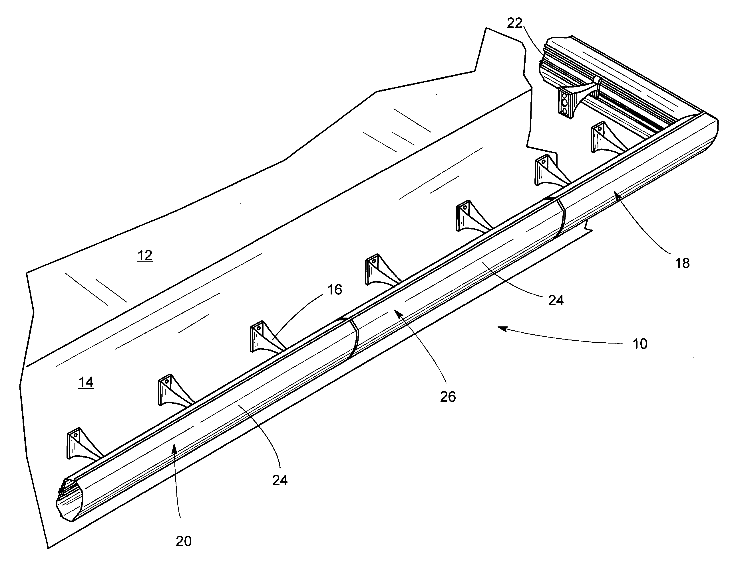
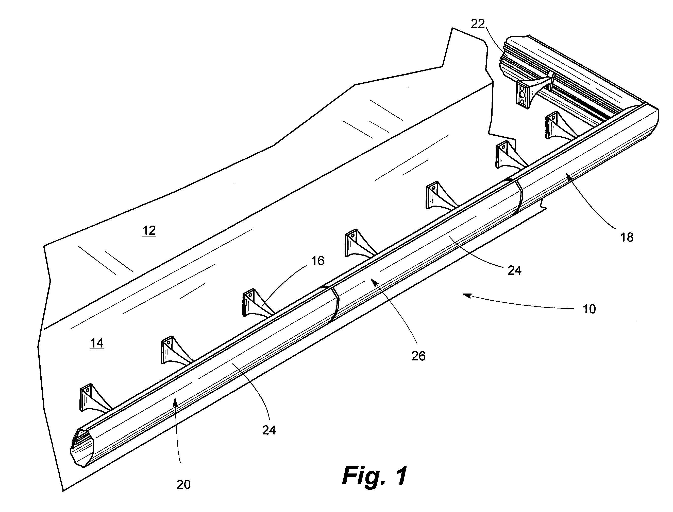
[0018]Referring now to the drawings and particularly to FIG. 1, an illuminated sign is seen at 10 to be configured according to the invention and is seen to be mounted to a building face 12 in juxtaposition to a reflective fascia 14 by means of mounts 16 which are mounted to or through the fascia 14 to the face 12 of a building. The sign 10 is seen in an installation on a canopy of a service station or the like. The illuminated sign 10 functions primarily to provide a visual affect intended to be decorative and also to identify at least in certain situations a particular commercial presence that is associated with the form of the illuminated sign 10 and also with coloration of the sign 10 and of the fascia 14. It is to be understood that an installation need not be provided with the reflective fascia 14 as desired according to the exigencies of a particular situation. The sign 10 is formed of an illuminated a corner section 18 as well as at least one illuminated sections 20, the sec...


PUM


Abstract

Apparatus permitting adjustment of the length of a section of an illuminated sign such as is used to provide a visual indication of a particular service provided by a given vendor, such as a vendor of service station products and services, the invention provides for fitting of a last section of a succession of sections to a particular lengthwise dimension mandated by the structure to which the illuminated sign is mounted. Illumination sources, particularly sets of light emitting diodes, cause both forwardly and rearwardly directed light to be respectively diffused through a diffuser or reflected from a surface to which the sign is mounted to provide a glow yielding the intended visual affect. At least certain of the light emitting diodes are mounted by sliding elements movable along an elongated track to permit location of said light emitting diodes in an appropriate location within a section which has been trimmed to an appropriate length, thereby providing a desired illumination along the length of the trimmed section or along the length of a section which does not require adjustment of its lengthwise dimension.

Description

BACKGROUND OF THE INVENTION [0001]1. Field of the Invention[0002]The invention relates generally to visual displays such as are used about upper portions of a periphery of building structure such as a service station to provide a degree of illumination and a visual indication assocaited with a particular vendor or the like, the invention particularly relating to an illuminated fascia of a canopy or the like having light emitting diodes as the illumination source mounted by sections at least one of which can be trimmed to length as necessary to fit within a succession of sections intended to accommodate particular dimensions of an installation.[0003]2. Description of the Prior Art[0004]Buildings are commonly provided with illuminated fascia intended primarily to provide a visual indication of a commercial service associated with a particular vendor, such illuminated fascia typically being disposed about upper peripheral portions of a building with which commercial activity is associa...

Claims


Application Information

Patent Timeline
Patent Type & Authority Patents(United States)
IPC IPC(8): F21S4/00
CPCG09F13/22
Inventor YATES, JAMES P.
Owner YATES JAMES P
Why Eureka
Try Eureka