Surgical drill guide

a drill guide and surgical technology, applied in the field of surgical drill guides, can solve the problems of complex adjustment of known drill guides, lack of any type of incremental adjustment, and inability to meet the needs of patients, and achieve the effect of facilitating engagement with the fixed stop

Active Publication Date: 2006-11-07
SYNTHES USA
View PDF97 Cites 51 Cited by
  • Summary
  • Abstract
  • Description
  • Claims
  • Application Information

AI Technical Summary

Benefits of technology

[0006]The first drill guide body and the second drill guide may body define a common longitudinal axis. The second drill guide body may be slidable within the first drill guide body, or vice versa. The first drill guide body and / or the second drill guide body may comprise a substantially tubular shaft. The distal end of the first drill guide body may include at least two projections for engaging the bone. The proximal end of the second drill guide body may in operation engage a fixed stop on a drill bit. The proximal end of the second drill guide body may include an enlarged diameter head which may facilitate engagement with the fixed stop.

Problems solved by technology

Known drill guides may also lack any type of incremental adjustment of the hole depth, which may also add to the time required for the adjustment process.
Further, known drill guides are often complicated to adjust.

Method used


Image

  • Surgical drill guide
  • Surgical drill guide
  • Surgical drill guide

Examples


Embodiment Construction

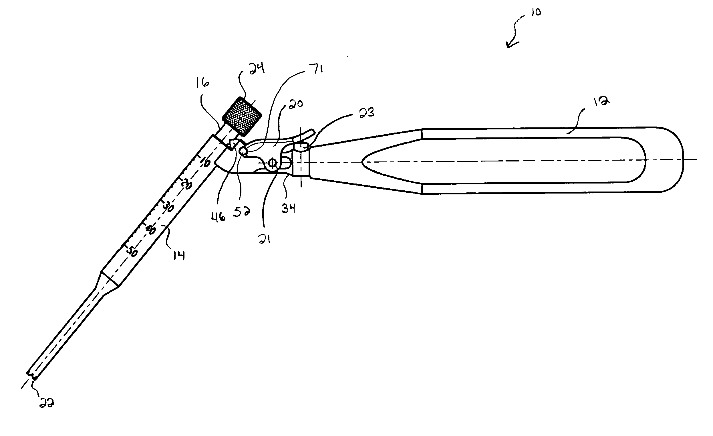
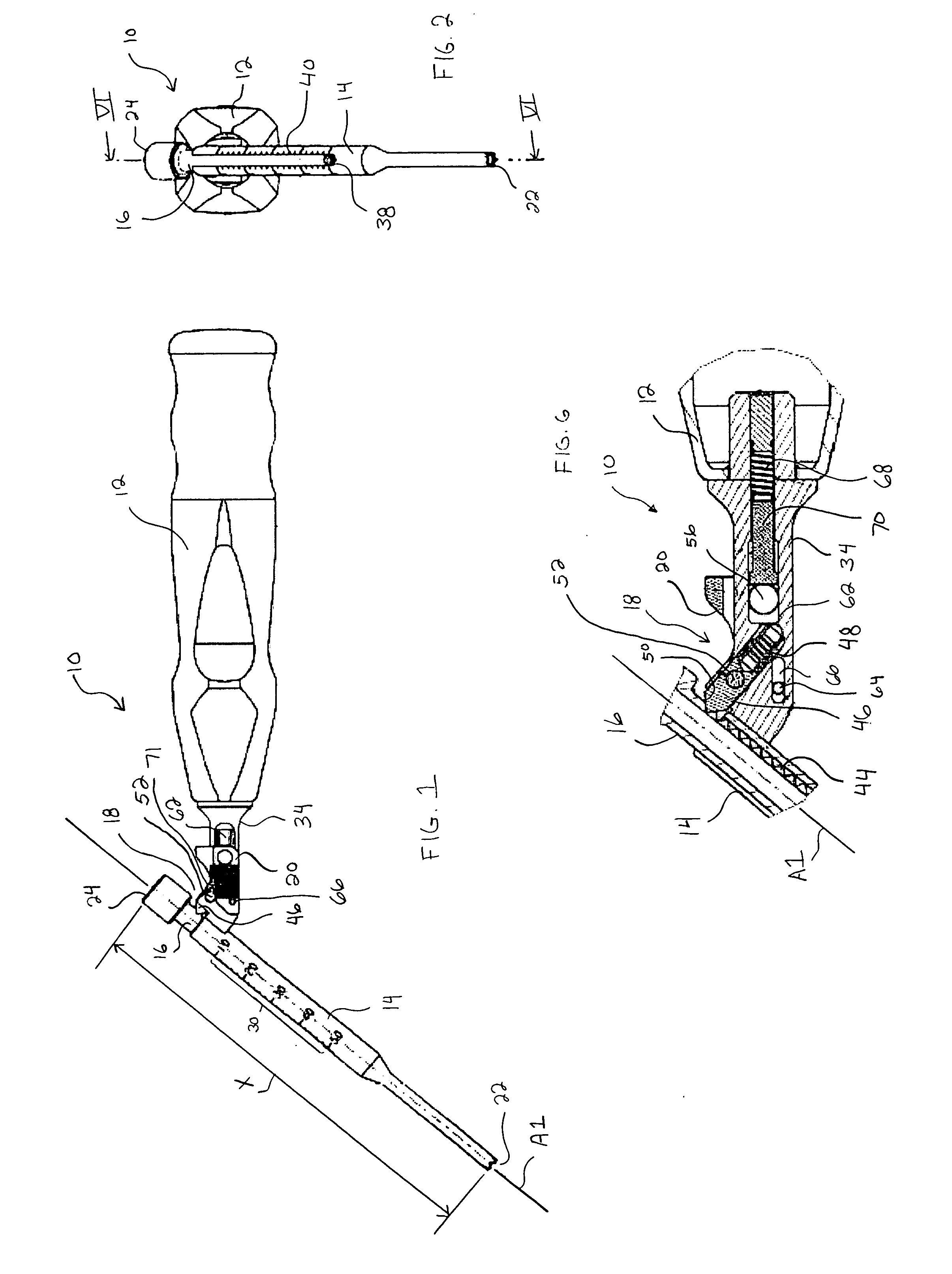
[0026]Referring to FIGS. 1 and 2, an illustrative embodiment of a surgical drill guide according to the present invention is shown. Drill guide 10 may generally include a handle 12, a first drill guide body 14, and a second drill guide body 16. Drill guide 10 may also include a detent mechanism 18 (such as shown in detail in FIG. 6) and / or a locking member 20. First drill guide body 14 and second drill guide body 16 may be substantially tubular shafts that slide or telescope with respect to one another. According to one preferred embodiment, second drill guide body 16 may slide within first drill guide body 14 along a common longitudinal axis A1, however other configurations are possible. When second drill guide body 16 is received within first drill guide body 14, the first and second drill guide bodies 14, 16 preferably define a common cannula for receiving a drill bit. By holding the drill guide 10 by its handle 12 and inserting a drill bit through the cannula, the user may contr...


PUM


Abstract

The present invention is directed to a surgical drill guide. The drill guide may include a first drill guide body having a distal end for placement substantially adjacent a bone, a second drill guide body slidable with respect to the first drill guide body and having a proximal end for contacting a portion of a drill bit, a handle associated with at least one of the first drill guide body and the second drill guide body, and a detent mechanism for releasably retaining the position of the first drill guide body with respect to the second drill guide body in predefined increments. Additionally or alternatively, the drill guide may include a locking member movable between a first position where it substantially prevents sliding of the second drill guide body with respect to the first drill guide body, and a second position where it permits sliding of the second drill guide body with respect to the first drill guide body. The locking member may be resiliently biased to the first position. Other features for improving the drill guide are disclosed and claimed as well.

Description

TECHNICAL FIELD OF THE INVENTION[0001]The present invention relates generally to surgical drill guides. More specifically, the present invention relates to surgical drill guides for positioning, orienting and measuring the depth of holes to be drilled in bone tissue.BACKGROUND OF THE INVENTION[0002]It is well known to drill holes in bones in order to accommodate fastening devices used to anchor implants within a patient's body. For instance, pedicle screws have been used to anchor instrumentation systems to the spinal column of patients for correcting a variety of spinal disorders. One commonly used technique for inserting a pedicle screw into the bone includes the preparation of a pilot hole through the pedicle before inserting the screw therein. Typically, the selection of the insertion point is made based on the anatomy of the vertebra. Once the insertion point has been selected, a drill guide may be used to guide the drill bit along the proper axis, and / or to set the depth to wh...

Claims


Application Information

Patent Timeline
Patent Type & Authority Patents(United States)
IPC IPC(8): A61B17/02A61BA61B17/16A61B17/17A61B17/58A61B19/00
CPCA61B17/1622A61B17/17A61B17/1615A61B17/1671A61B17/1757A61B2019/462A61B2090/062
Inventor KEYER, THOMAS R.BERGER, ROGERKEPHART, DOUGLAS S.WALTHER, MARTIN
Owner SYNTHES USA
Why Eureka
Try Eureka