Image forming apparatus and image forming method

a technology of image forming apparatus and forming method, which is applied in the direction of electrographic process apparatus, printing, instruments, etc., can solve the problems of conventional image forming apparatus, positional shift among respective color images, and uneven rotation among rotating members, so as to suppress the interruption of image formation and high-quality image output

Active Publication Date: 2006-11-07
KONICA MINOLTA BUSINESS TECH INC
View PDF8 Cites 21 Cited by
  • Summary
  • Abstract
  • Description
  • Claims
  • Application Information

AI Technical Summary

Benefits of technology

[0009]The present invention has been made in order to solve the foregoing problems. It is intended to provide an image forming apparatus and image forming method capable of obtaining a considerable high-quality image output even under a correction mode that gives preference to processing time required for correction, and capable of suppressing interruption of image formation to the utmost under operational condition such that internal temperature changes continuously.

Problems solved by technology

That is, there occur uneven rotation among rotating members such as photosensitive drums of respective image forming section and uneven running of a carrying belt, due to degree of mechanical accuracy or the like.
That is, heat expansion occurring to each section due to internal temperature potentially causes positional shift among respective color images.
However, those conventional image forming apparatuses have had the following problems.
As to No. 8-305108, color shift correction could not be conducted appropriately under operational condition such that internal temperature changes continuously, e.g., during multi-printing operation or the like.
Therefore, actual productivity was poor.

Method used


Image

  • Image forming apparatus and image forming method
  • Image forming apparatus and image forming method
  • Image forming apparatus and image forming method

Examples


Embodiment Construction

[0029]Reference will now be made in detail to presently a preferred embodiment of the invention as illustrated in the accompanying drawings. The present embodiment is applicable to a tandem-type color printer or a digital color copier.

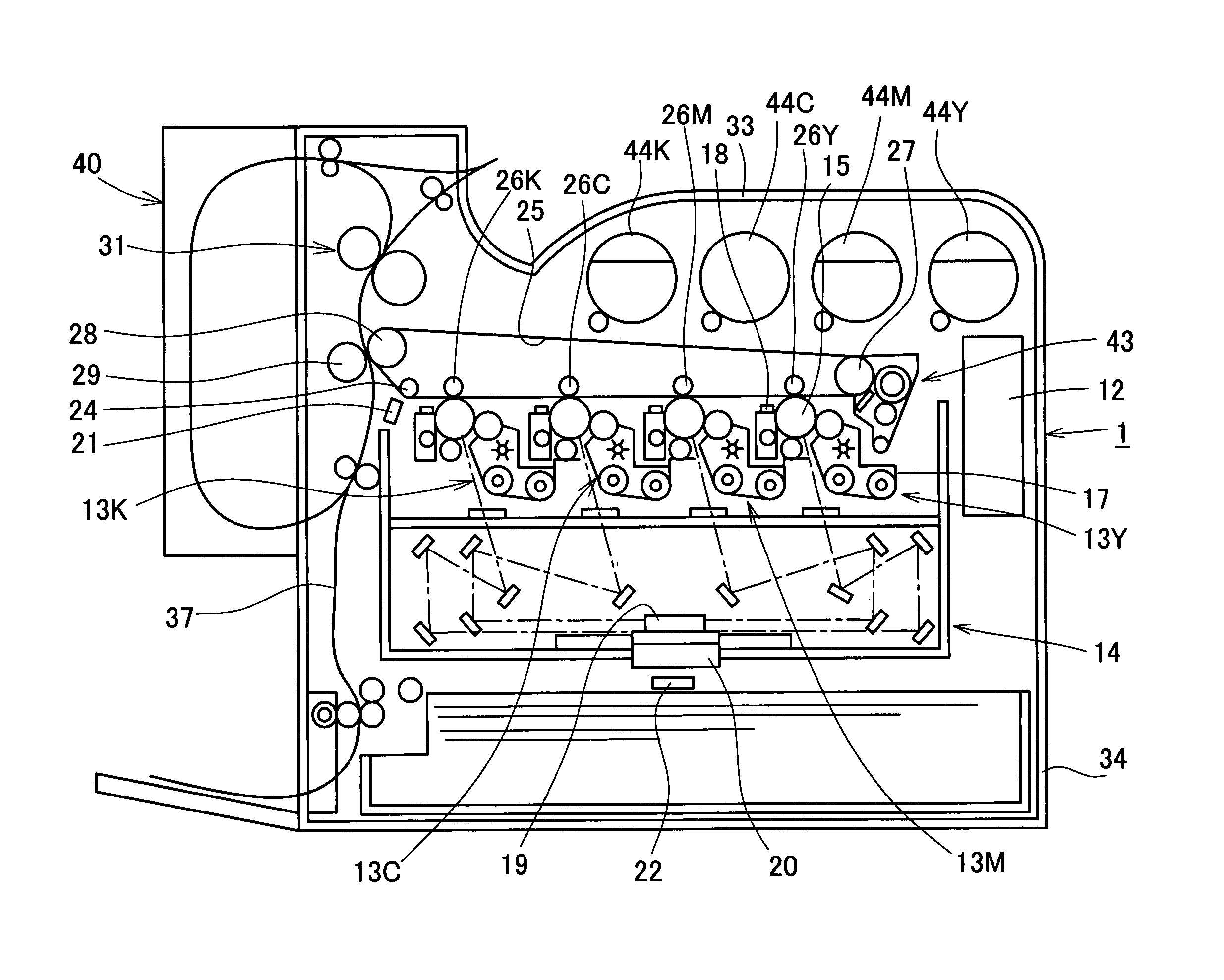
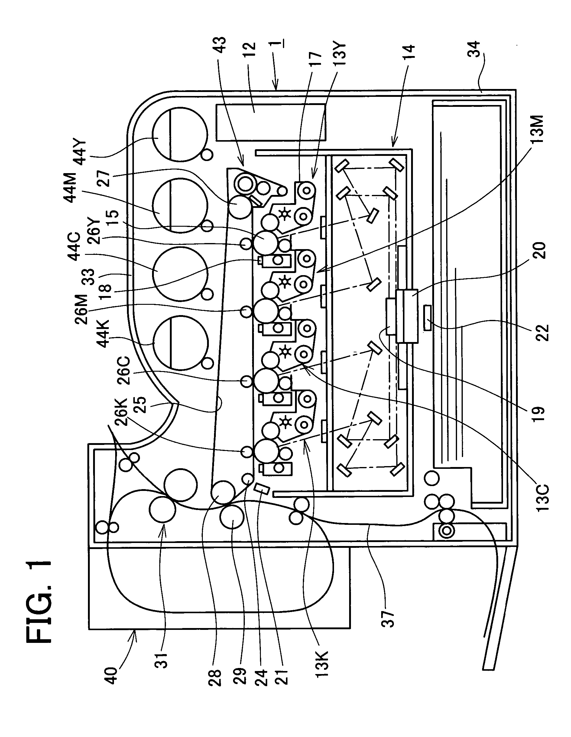
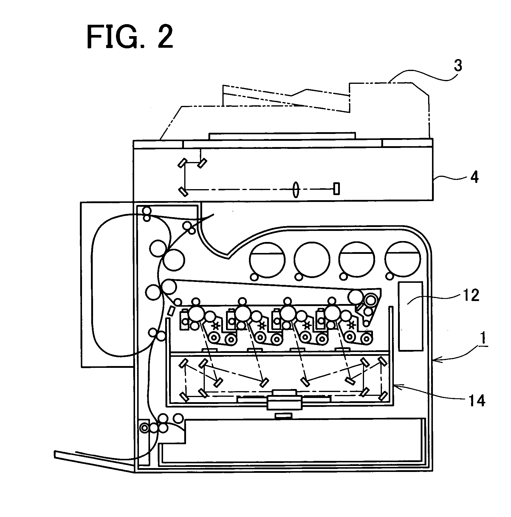
[0030]A digital color printer 1 of the present embodiment is structured such as shown in FIG. 1. As shown in FIG. 2, a digital color copier of the present embodiment incorporates the digital color printer 1, an automatic document feeding apparatus 3 and an image reading apparatus 4.

[0031]The digital color printer 1 is mainly constituted by a loop-type intermediate transfer belt 25, and image forming units 13K (black), 13C (cyan), 13M (magenta), 13Y (yellow) arranged in a horizontal direction with reference to the intermediate transfer belt 25 with constant distance being taken between adjacent image forming units. Each of the image forming units 13K through 13Y has a well-known photosensitive drum 15, a developer 17, a cleaner 18, and the like. A print...


PUM


Abstract

It is intended to provide an image forming apparatus and image forming method capable of obtaining a comparatively high-quality image output even under a correction mode that gives preference to processing time required for correction, and capable of suppressing interruption of image formation to the utmost under operational condition such that internal temperature changes continuously. There are saved last five detections of positional shift quantity under first correction mode that gives preference to correction accuracy for each temperature band. Under second correction mode that gives preference to processing time required for correction, there is calculated a difference of a value actually obtained through measurement and an average value of data history belonging to a target temperature band (#7 through #9). Furthermore, the difference is multiplied by a reliability coefficient of main scanning direction and that of sub scanning direction, respectively, to determine correction quantity (#10, #11). Thereby, excessive change of correction quantity is prevented.

Description

[0001]This application is based on Application No. 2003-87965 filed in Japan, contents of which is hereby incorporated by reference.BACKGROUND OF THE INVENTION[0002]1. Field of the Invention[0003]The present invention relates to an image forming apparatus and image forming method wherein independent plural image forming units form primary images respectively and those primary images are superimposed on a medium to form a resultant image. More particularly, it relates to an image forming apparatus and image forming method that conducts positional correction with respect to superimposing position of each primary image.[0004]2. Description of Related Art[0005]There have been used tandem-type image forming apparatuses such as color printers, color copiers, and the like, wherein independent plural image forming sections for each color form their respective single color images and the single color images are superimposed on a carrying belt or on printing material mounted on the carrying b...

Claims


Application Information

Patent Timeline
Patent Type & Authority Patents(United States)
IPC IPC(8): G03G15/01B41J2/385B41J2/44G03G15/00G03G15/16H04N1/047H04N1/113H04N1/12H04N1/29
CPCG03G15/0131H04N1/0473G03G15/5058G03G2215/00059G03G2215/0119G03G2215/0161H04N1/1135H04N1/12H04N2201/0471H04N2201/04758H04N2201/04722H04N2201/02439H04N2201/04794
Inventor TANAKA, TOMOJIHABA, KENYAHINO, HIDEKI
Owner KONICA MINOLTA BUSINESS TECH INC
Why Eureka
Try Eureka