
Polymer optical waveguide and method of making the same

a technology of optical waveguides and polymer fibers, applied in the direction of optical waveguide light guides, instruments, optics, etc., can solve the problems of affecting the optical characteristics of the polymer optical waveguides more badly, the main body of the waveguide may be peeled off from the main body of the polymer optical waveguide, and the heat-shock resistance of the material is disadvantageous, so as to achieve good heat-shock properties and temperature characteristics. good

Inactive Publication Date: 2006-11-07
HITACHI METALS LTD
View PDF7 Cites 17 Cited by
  • Summary
  • Abstract
  • Description
  • Claims
  • Application Information

AI Technical Summary

Benefits of technology

[0014]It is an object of the invention to provide a polymer optical waveguide that has a good heat-shock property and temperature characteristic.

Problems solved by technology

There is a worry that these materials are disadvantageous in heat or moisture resistance since they can be subjected to a variation in refractive index or optical loss under high temperature and high humidity.
In this case, the optical characteristics of the polymer optical waveguide will be affected more badly.
However, the polymer optical waveguide using a material with a high glass transition temperature has problems that the waveguide main body may be peeled off from the polymer waveguide main body or cracked when subjected to a heat-shock test (e.g., a test that the surrounding temperature is repeatedly increased and decreased in the temperature range of −40 to 85° C.) since where the waveguide main body is formed directly on the substrate.
Therefore, if the clad layer of '399 is directly used for the polymer optical waveguide, the buffering effect will be insufficient.
Further, since the clad layer of '399 is made of glass, it is difficult to process as compared to resins and therefore the manufacturing cost increases.

Method used


Image

  • Polymer optical waveguide and method of making the same
  • Polymer optical waveguide and method of making the same
  • Polymer optical waveguide and method of making the same

Examples


Embodiment Construction

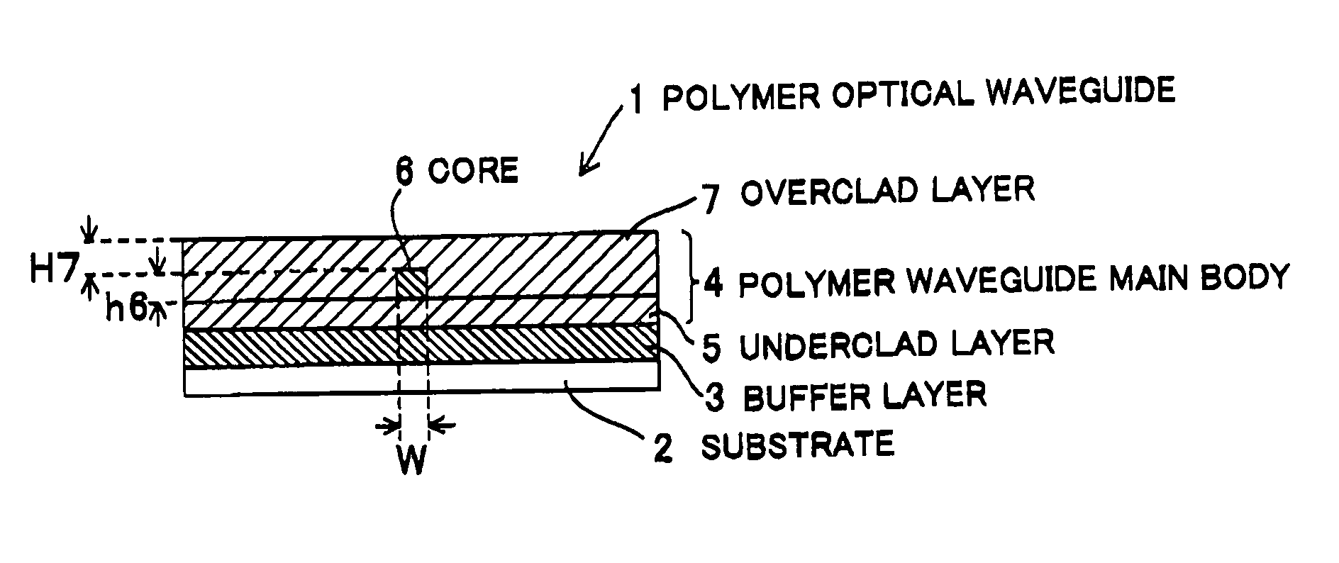
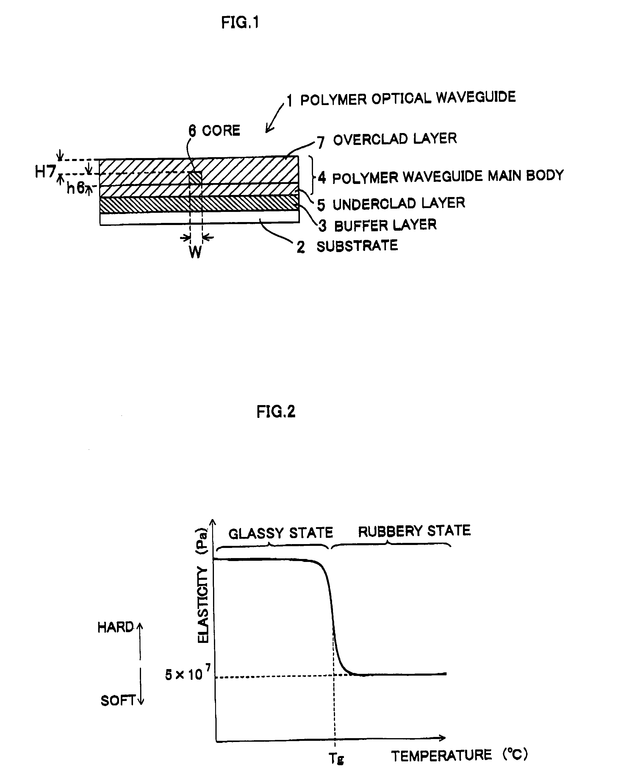
[0044]FIG. 1 is a cross sectional view showing a polymer optical waveguide 1 in the preferred embodiment according to the invention.

(Composition of the Polymer Optical Waveguide 1)

[0045]As shown in FIG. 1, the polymer optical waveguide 1 of this embodiment is composed of: a substrate 2; a buffer layer 3 formed on the substrate 2; and a polymer waveguide main body 4 formed on the buffer layer 3.

[0046]The substrate 2 is made of an inorganic material such as Si and silica glass. In this embodiment, the substrate 2 used is a Si wafer (=Si substrate) of 400 μm in thickness.

[0047]The polymer waveguide main body 4 is made of a polymer with a linear expansion coefficient different from that of the substrate 2. The polymer waveguide main body 4 is composed of: an underclad (=lower clad) layer 5; a core 6 formed on the underclad layer 5; and an overclad (=upper clad) layer 7 that covers the upper surface of the underclad layer 5 and the core 6.

[0048]In this embodiment, the polymer may be poly...


PUM

PropertyMeasurementUnit
glass transition temperatureaaaaaaaaaa
temperatureaaaaaaaaaa
thicknessaaaaaaaaaa

Abstract

A polymer optical waveguide has a substrate, a buffer layer formed on the substrate, and a polymer waveguide main body formed on the buffer layer. The buffer layer is made of a polymer material that can absorb a difference in thermal expansion coefficient between the substrate and the polymer optical waveguide.

Description

[0001]The present application is based on Japanese patent application No. 2004-365750, the entire contents of which are incorporated herein by reference.BACKGROUND OF THE INVENTION[0002]1. Field of the Invention[0003]This invention relates to a polymer optical waveguide with a buffer layer and a method of making the polymer optical waveguide.[0004]2. Description of the Related Art[0005]In recent years, polymer optical waveguides made of a polymer material are researched and developed since they are advantageous in workability and manufacturing cost as compared to glass optical waveguides made of a glass material.[0006]Various polymer materials for a waveguide main body formed on a substrate are suggested, for example, acrylic (See Japanese patent application laid-open No. 10-170739), epoxy (See Japanese patent application laid-open No. 2002-286953), and polyimide (See Japanese patent application laid-open No. 2003-215364). There is a worry that these materials are disadvantageous in...

Claims


Application Information

Patent Timeline
Patent Type & Authority Patents(United States)
IPC IPC(8): G02B6/10
CPCG02B6/1221G02B6/138
Inventor YASUDA, HIROKIHIRANO, KOUKIABE, TOMIYAITO, YUZO
Owner HITACHI METALS LTD
Learn More