Supercharge Your Innovation With Domain-Expert AI Agents!

Sensor with symmetrical limiting of a signal

a technology of symmetrical limit and signal, applied in the direction of instruments, devices using electric/magnetic means, acceleration measurement using interia forces, etc., can solve problems such as deviation, and achieve the effect of simple and proven principle, easy to measure, and easy to be further processed

Active Publication Date: 2006-11-14
ROBERT BOSCH GMBH
View PDF5 Cites 10 Cited by
  • Summary
  • Abstract
  • Description
  • Claims
  • Application Information

AI Technical Summary

Benefits of technology

[0007]The sensor of the present invention has the advantage that an asymmetrical limiting of the signal is replaced by a symmetrical limiting. Under certain conditions during operation, such as, for example, the influence of broken stone or spray water, the deflection of the seismic mass represents a periodic signal whose time average is essentially constant. If the deflection were limited asymmetrically, the average value would be changed. After a subsequent filtering in the signal path, this altered value would be interpreted falsely as a very great constant acceleration acting on the sensor. On the other hand, if the signal is limited symmetrically, then the average value is retained in comparison to a vibrator which is not limited by a stop.
[0010]One advantageous development of the sensor according to the present invention is that the means for detecting the deflection take the form of electrodes which represent a capacitive detecting element, particularly according to the principle of differential capacitance. This is a simple and proven principle for measuring deflections when working with micromechanical acceleration sensors and rotation-rate sensors. The variable capacitance can be easily measured using an electronic evaluation circuit connected thereto, and the electrical measured values obtained may easily be further processed.
[0011]In one particularly advantageous refinement, the means for limiting the maximum value of the electrical signal are represented by an electronic evaluation circuit. The electrical limiting of the maximum values of the electrical signal is advantageously carried out in a simple manner in an electronic evaluation circuit.

Problems solved by technology

However, this deviation may change due to ageing or changing environmental conditions.

Method used


Image

  • Sensor with symmetrical limiting of a signal
  • Sensor with symmetrical limiting of a signal
  • Sensor with symmetrical limiting of a signal

Examples


Embodiment Construction

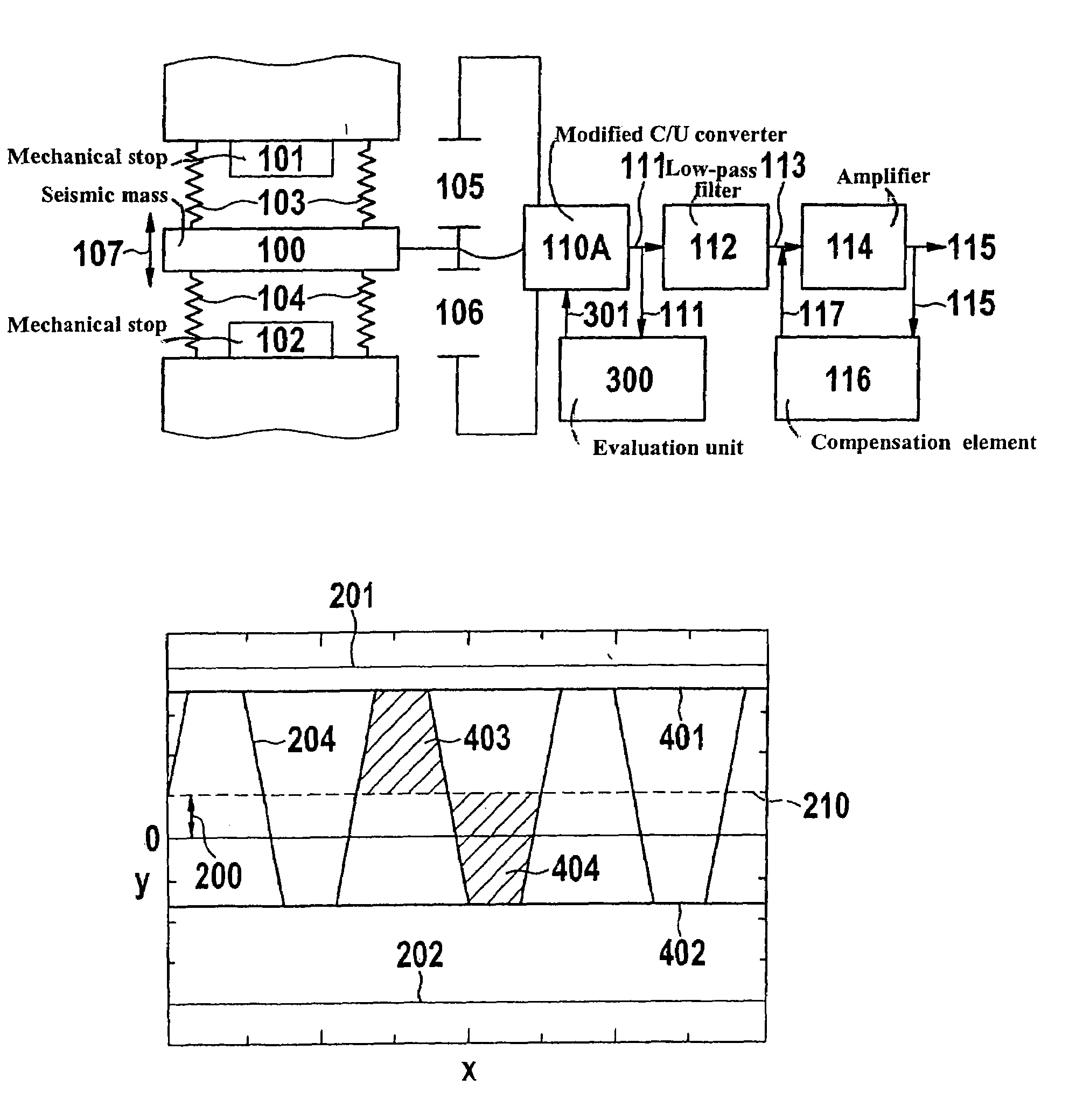
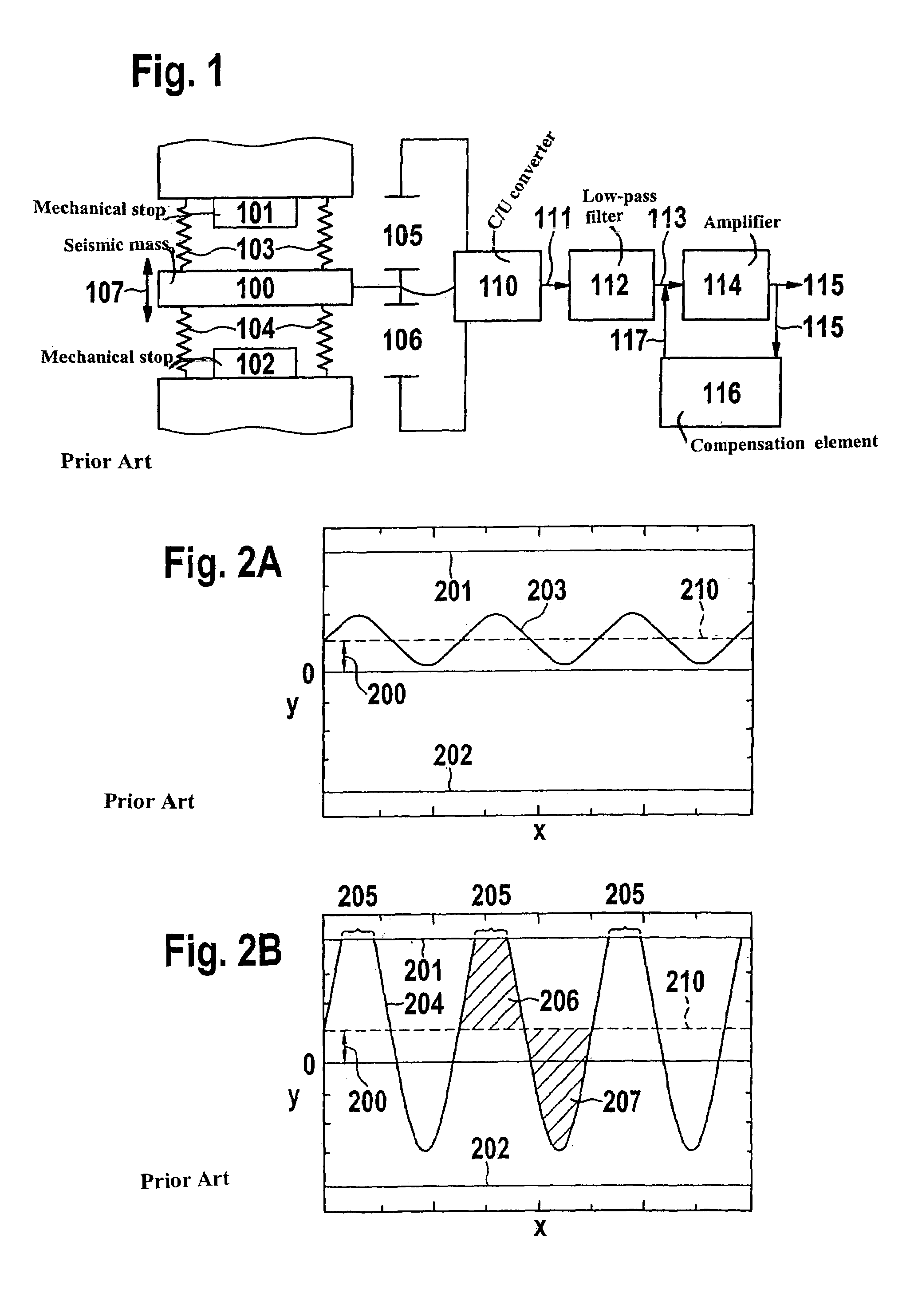
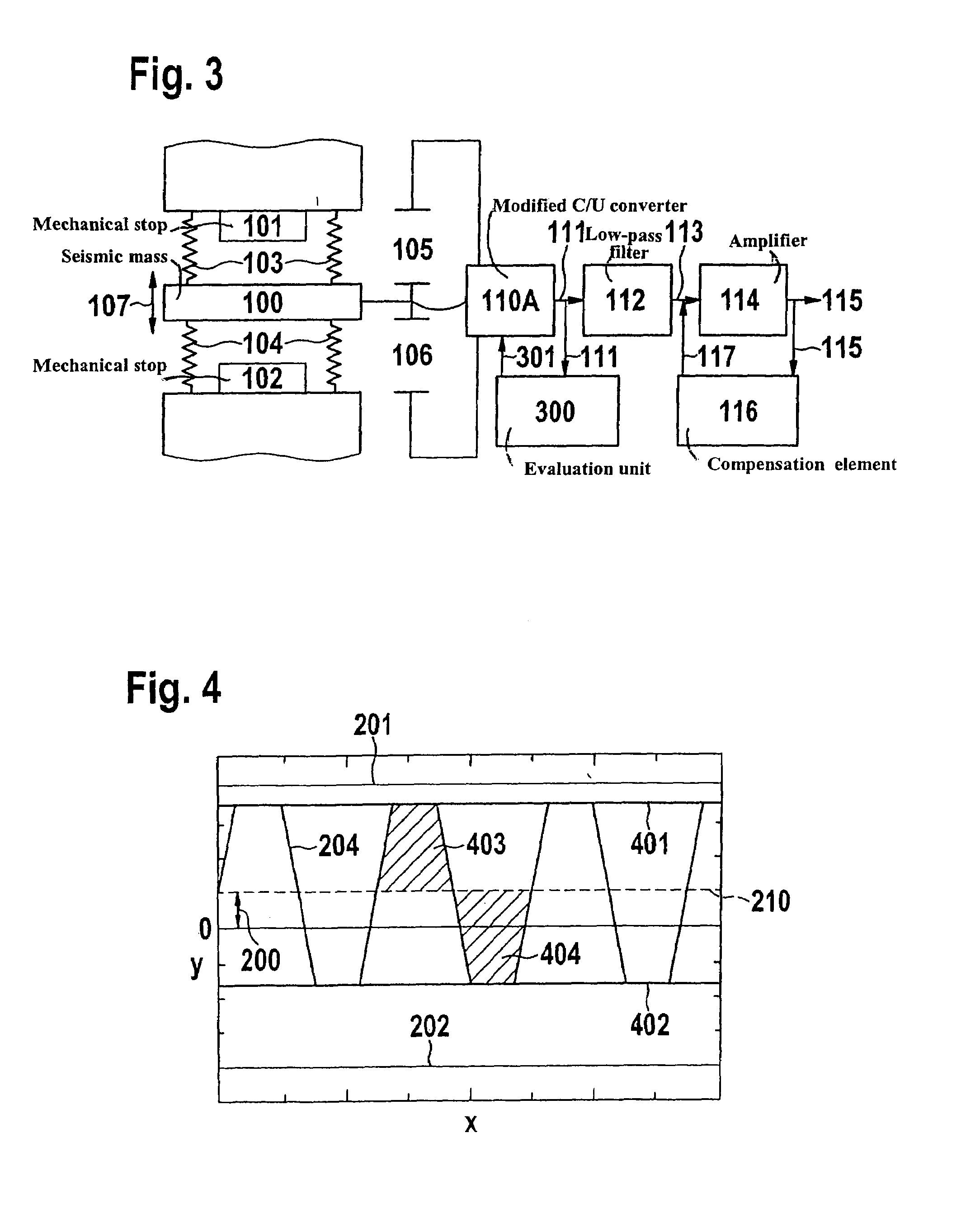
[0021]FIG. 1 shows an inertial sensor according to the related art. A seismic mass 100 is suspended by a system of springs 103, 104 in a manner allowing vibration. The deflection or vibration of seismic mass 100 induced by an external force takes place in a direction 107. The maximum possible deflection of mass 100 is limited in this example by two mechanical stops 101 and 102. Movable mass 100 represents a movable electrode, and together with two fixed reference electrodes, forms two capacitances 105 and 106. Capacitances 105 and 106 change as a function of the deflection of the mass along direction 107. The detecting element operates according to the principle of differential capacitance. The difference of capacitances 105 and 106 is converted in a capacitance / voltage converter (C / U converter) 110 into a voltage signal 111 essentially proportional to the acceleration. Voltage signal 111 is filtered in a low-pass filter 112 which, for example, may be a filter with switched capacita...


PUM


Abstract

A sensor having a seismic mass and having an arrangement for detecting the deflection of the mass and converting it into an electrical signal; in at least one operating mode of the sensor, a mechanical stop asymmetrically limiting the deflection of the seismic mass with respect to a vibrational center position. An arrangement for symmetrical limiting of the signal provided on the sensor.

Description

BACKGROUND INFORMATION[0001]Accelerations in motor vehicles, particularly in their airbag control units, are measured using micromechanical inertial sensors. In so doing, the principle of the differential capacitor is used, in which a movable seismic mass, together with fixed reference electrodes, forms two capacitances. If an acceleration acts on the mass, it is deflected and the capacitances change. The difference in the capacitances is converted by an electronic circuit, a so-called capacitance / voltage converter (C / U converter), into a voltage signal essentially proportional to the acceleration. The movable structures and the capacitor-like arrangements, which form the capacitances, are usually implemented as microelectromechanical structures (MEMS).[0002]The precise centering of the seismic mass between the fixed electrodes represents a problem when manufacturing the inertial sensors in the construction as MEMS. As a rule, the actual position of the seismic mass deviates from th...

Claims


Application Information

Patent Timeline
Patent Type & Authority Patents(United States)
IPC IPC(8): G01P15/13G01P15/125G01P9/04G01P3/42G01P15/00G01P15/08
CPCG01P15/08G01P15/125
Inventor GAHN, CHRISTOPHDROSTE, DIRK
Owner ROBERT BOSCH GMBH
Features
  • R&D
  • Intellectual Property
  • Life Sciences
  • Materials
  • Tech Scout
  • Unparalleled Data Quality
  • Higher Quality Content
  • 60% Fewer Hallucinations
Learn More