
Isolation assembly for coiled tubing

a technology of isolation assembly and coiled tubing, which is applied in the direction of fluid removal, borehole/well accessories, construction, etc., can solve the problems of high pressure generation, and achieve the effect of reducing pipe cos

Active Publication Date: 2006-11-14
BAKER HUGHES INC
View PDF26 Cites 62 Cited by
  • Summary
  • Abstract
  • Description
  • Claims
  • Application Information

AI Technical Summary

Benefits of technology

[0017]In some embodiments, utilizing the disclosed isolation assembly allows the internal surface coiled tubing pressure to be reduced to approximately zero (i.e. atmospheric pressure) in a timely manner before cycling the coiled tubing, which may significantly reduce the cost of pipe (by a factor of 6.8, per estimates, as shown on Table 1 hereinafter).

Problems solved by technology

In some embodiments, the frac fluid or stimulation fluid disclosed is nitrogen gas, liquid or gaseous carbon dioxide, water based fluids, hydrocarbon based fluids, or a mixture of any of these fluids, which may result in high pressures being generated.

Method used


Image

  • Isolation assembly for coiled tubing
  • Isolation assembly for coiled tubing
  • Isolation assembly for coiled tubing

Examples


Embodiment Construction

[0030]Illustrative embodiments of the invention are described below as they might be employed in performing an operation, such as performing a fracing or stimulation operation, for example. In the interest of clarity, not all features of an actual implementation are described in this specification. It will of course be appreciated that in the development of any such actual embodiment, numerous implementation specific decisions must be made to achieve the developers' specific goals which will vary from one implementation to another. Moreover, it will be appreciated that such a development effort might be complex and time-consuming, but would nevertheless be a routine undertaking for those of ordinary skill in the art having the benefit of this disclosure. Further aspects and advantages of the various embodiments of the invention will become apparent from consideration of the following description and drawings.

[0031]The following examples are included to demonstrate preferred embodime...


PUM


Abstract

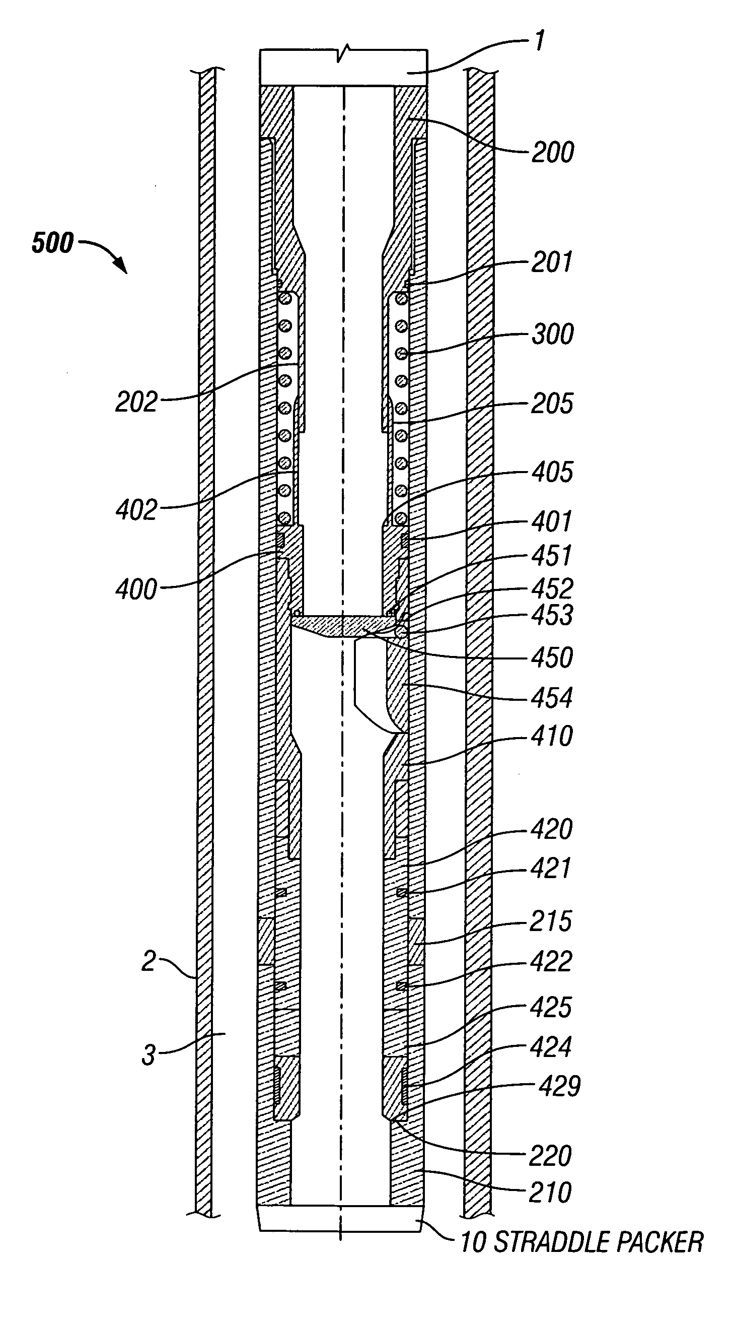
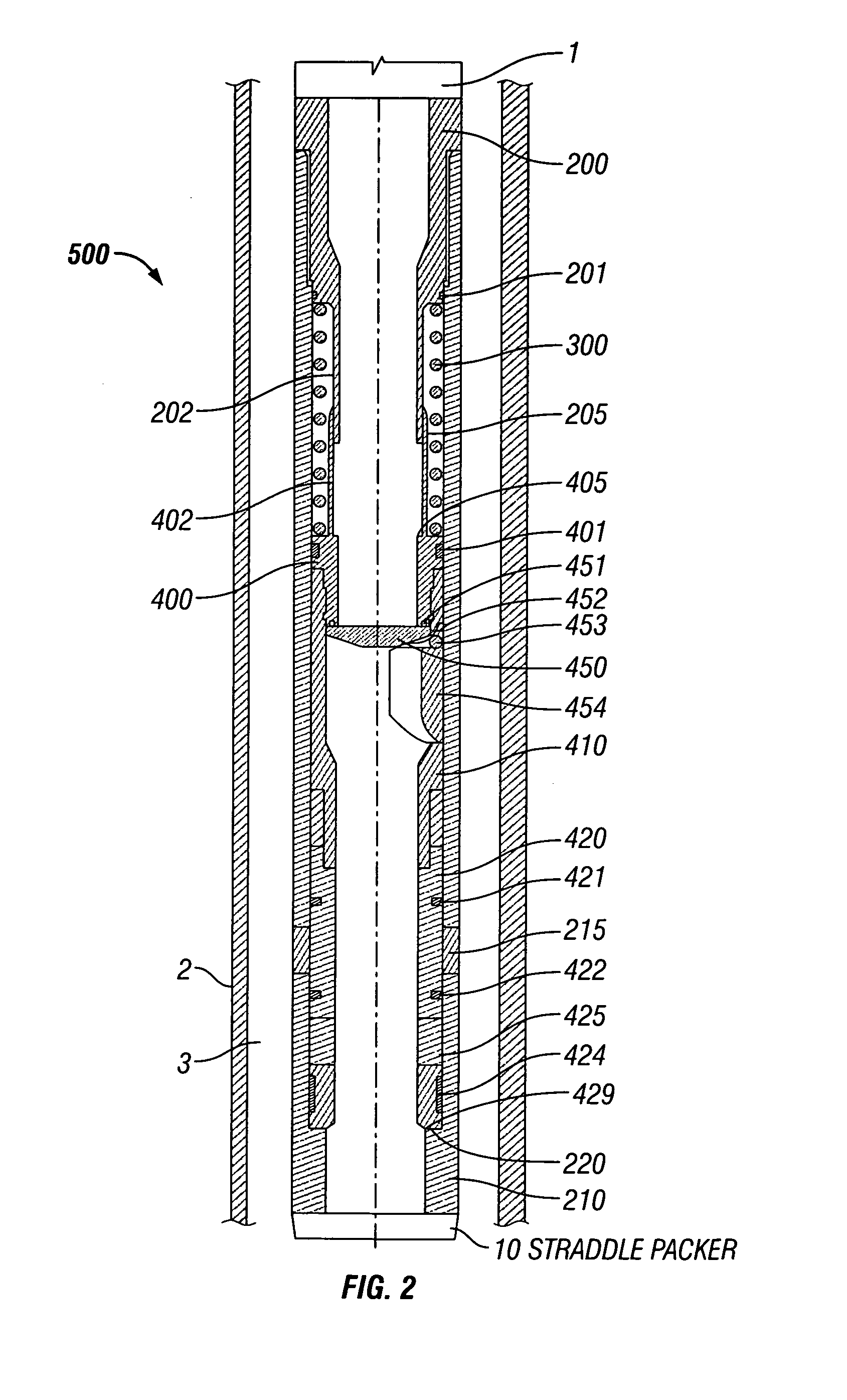
An isolation assembly for use with coiled tubing is described. The isolation assembly has a check valve for providing selective fluid communication through from the coiled tubing, through the isolation assembly, and into a downhole tool, such a straddle packer. The isolation assembly includes a shuttle moveable within a housing, and plurality of ports to selectively provide fluid communication from within the isolation assembly below the check valve, through the ports, and into the annulus, thus allowing selective surface-controlled equalization of downhole equipment. Also described is a bottom hole assembly including the isolation assembly. An improved method of fracing a formation includes providing a check valve, thus improving the life of the coiled tubing and the safety of the operation, and reducing the time to perform a given downhole operation.

Description

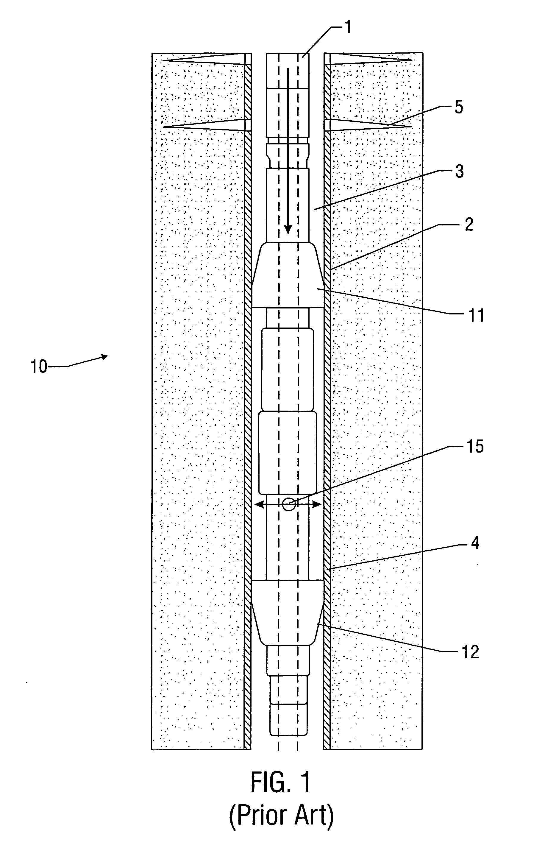
BACKGROUND OF THE INVENTION[0001]1. Field of the Invention[0002]The present invention relates generally to downhole tools for use in wellbores. More particularly, this invention relates to an isolation assembly for use with coiled tubing operations, such as the pressure testing, matrix stimulation, or fracturing (“fracing”) a well with a downhole tool, among other things.[0003]2. Description of the Related Art[0004]In the drilling and production of oil and gas wells, it is frequently necessary to isolate one subterranean region from another to prevent the passage of fluids between those regions. Once isolated, these regions or zones may be fraced or injected with a formation compatible fluid as required to stimulate production of hydrocarbons from the zones. Many stimulation techniques for given types of wells are better suited to using coiled tubing, as opposed to conventional jointed pipe intervention. Generally, it is known to attach a selective isolation device, such as a stradd...

Claims


Application Information

Patent Timeline
Patent Type & Authority Patents(United States)
IPC IPC(8): E21B43/25E21B23/00E21B23/06E21B33/12E21B33/124E21B34/00E21B34/06E21B43/26
CPCE21B33/124E21B2034/005E21B2200/05
Inventor TUDOR, ERIC HUGHSONGAVIN, WILLIAM GEORGE
Owner BAKER HUGHES INC
Learn More