
XFP adapter module

a technology of adapter module and adapter module, which is applied in the field of optical interfaces, can solve the problems of inability to redesign existing circuit packs to employ xfp modules, incompatible xfp modules with existing 300 pin msa transponders,

Active Publication Date: 2006-11-14
LUMENTUM FIBER OPTICS INC
View PDF3 Cites 26 Cited by
  • Summary
  • Abstract
  • Description
  • Claims
  • Application Information

AI Technical Summary

Benefits of technology

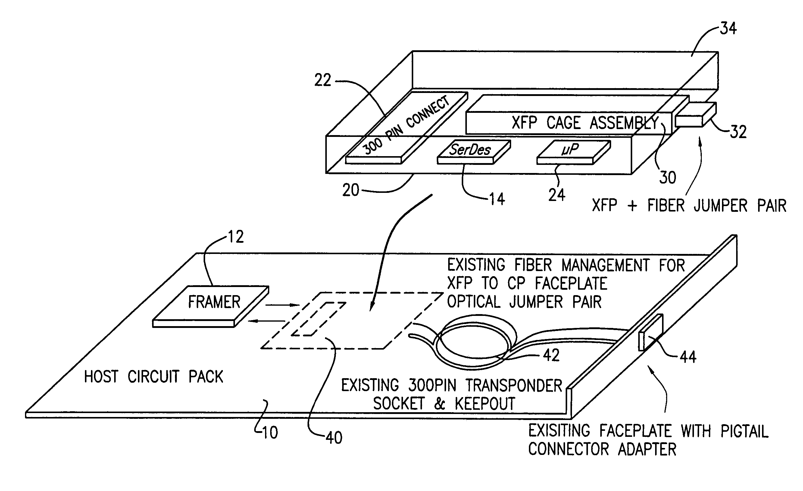
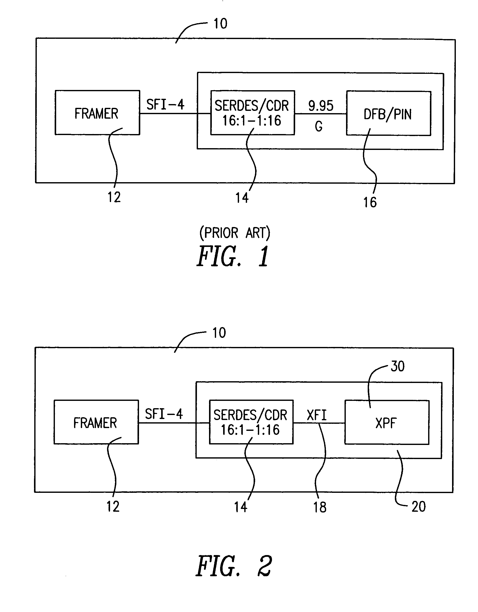
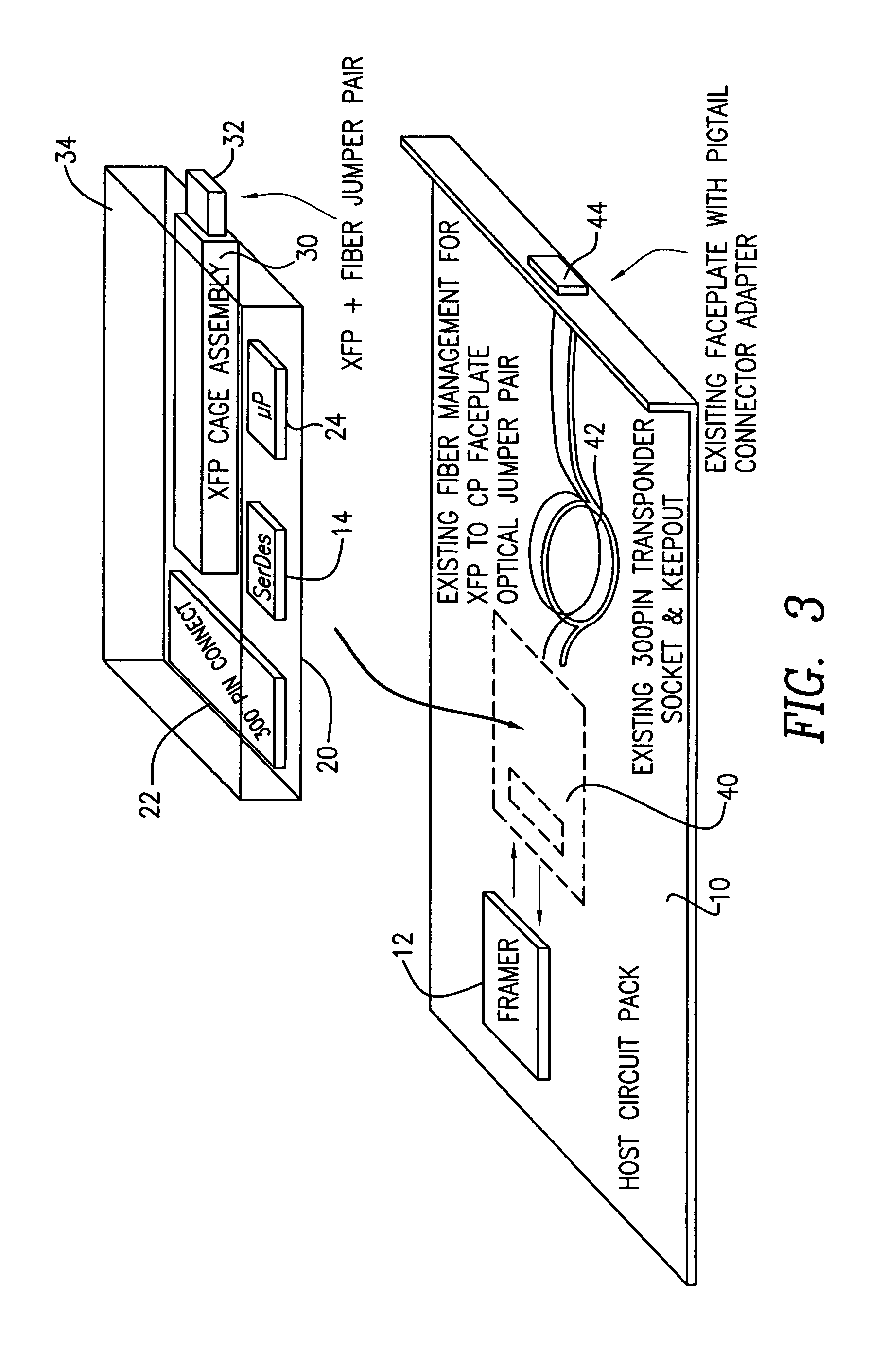
"The patent describes a device that allows for the replacement of a 300-pin MSA transponder with an XFP module on an existing host circuit pack. The device performs electronic dispersion compensation to address issues of jitter, path length equalization, cross talk, and electromagnetic compatibility. The device presents the attributes of XFP to the optical interface connection, fooling connected optical devices into reading a connection to XFP instead of the 300-pin MSA. The device also provides an alternative method of performing electronic dispersion compensation by performing it in a removable interface in a removable module."

Problems solved by technology

Currently, the XFP module is incompatible with existing 300 pin MSA transponders, and it is not practical to redesign existing circuit packs to employ the XFP module.

Method used


Image

  • XFP adapter module
  • XFP adapter module
  • XFP adapter module

Examples


Embodiment Construction

[0010]In the following description, for purposes of explanation, specific numbers, materials and configurations are set forth in order to provide a thorough understanding of the invention. It will be apparent, however, to one having ordinary skill in the art, that the invention may be practiced without these specific details. In some instances, well-known features may be omitted or simplified so as not to obscure the present invention. Furthermore, reference in the specification to “one embodiment” or “an embodiment” means that a particular feature, structure or characteristic described in connection with the embodiment is included in at least one embodiment of the invention. The appearances of the phrase “in one embodiment” in various places in the specification are not necessarily all referring to the same embodiment.

[0011]Now referring to FIG. 1 an existing 300 pin MSA circuit pack 10 is depicted. Framer 12 is connected via SERDES Framer Interface (SFI) such as SFI-4 to SERDES (P...


PUM


Abstract

A device which in an optical interface adapts XFP to a 300 pin MSA transponder socket, permitting replacement of 300 pin MSA transponders with an XFP module on an existing host circuit pack. The device performs dispersion compensation in a removable module, addressing issues of jitter, path length equalization, cross talk and electromagnetic compatibility. As deployed, the device presents at the optical interface the attributes of XFP, hence connected optical devices are “fooled” into reading a connection to XFP instead of the 300 pin MSA.

Description

TECHNICAL FIELD[0001]This invention relates to optical interfaces, and in particular to a device for adapting an “XFP” type interface to a 300 pin “MSA” type transponder socket and method for performing dispersion compensation in a removable module.BACKGROUND OF THE INVENTION[0002]In the past, optical interfaces were designed from discrete components. There have been many efforts to establish industrial standards in optical modules resulting in the formation of several Multi Source Agreements (MSA) including the 300 Pin MSA. This MSA specification consolidated this functionality into a 300 pin transponder. See, Reference Documents for 300 Pin 10 Gb and 40 Gb Transponders, available at www.300pinmsa.org, incorporated herein by reference. The industry has spent the last several years designing host circuit packs using MSA-based transponders.[0003]Over the past few years, technological advances have resulted in smaller such devices such as XFP. XFP is currently the most advanced MSA pr...

Claims


Application Information

Patent Timeline
Patent Type & Authority Patents(United States)
IPC IPC(8): G02B6/42H04J14/02
CPCH04B10/50H04B10/66
Inventor ANDERSON, JON
Owner LUMENTUM FIBER OPTICS INC
Learn More