
Flow compensation for turbine control valve test

a turbine control valve and flow compensation technology, applied in the direction of mechanical equipment, machines/engines, instruments, etc., can solve the problems of inability to modify, neither of these methods may be applied to the inlet pressure problem, and the pressure of the turbine steam boiler cannot change, so as to minimize the flow disturbance, improve performance, and minimize the effect of turbine power changes

Active Publication Date: 2006-11-14
GE INFRASTRUCTURE TECH INT LLC
View PDF4 Cites 2 Cited by
  • Summary
  • Abstract
  • Description
  • Claims
  • Application Information

AI Technical Summary

Benefits of technology

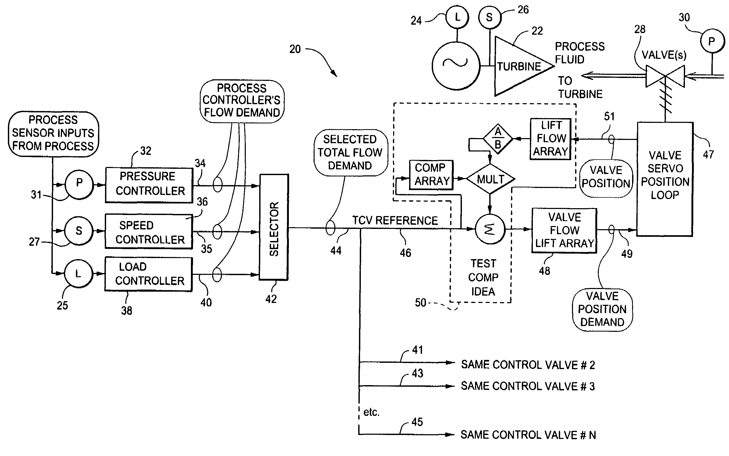
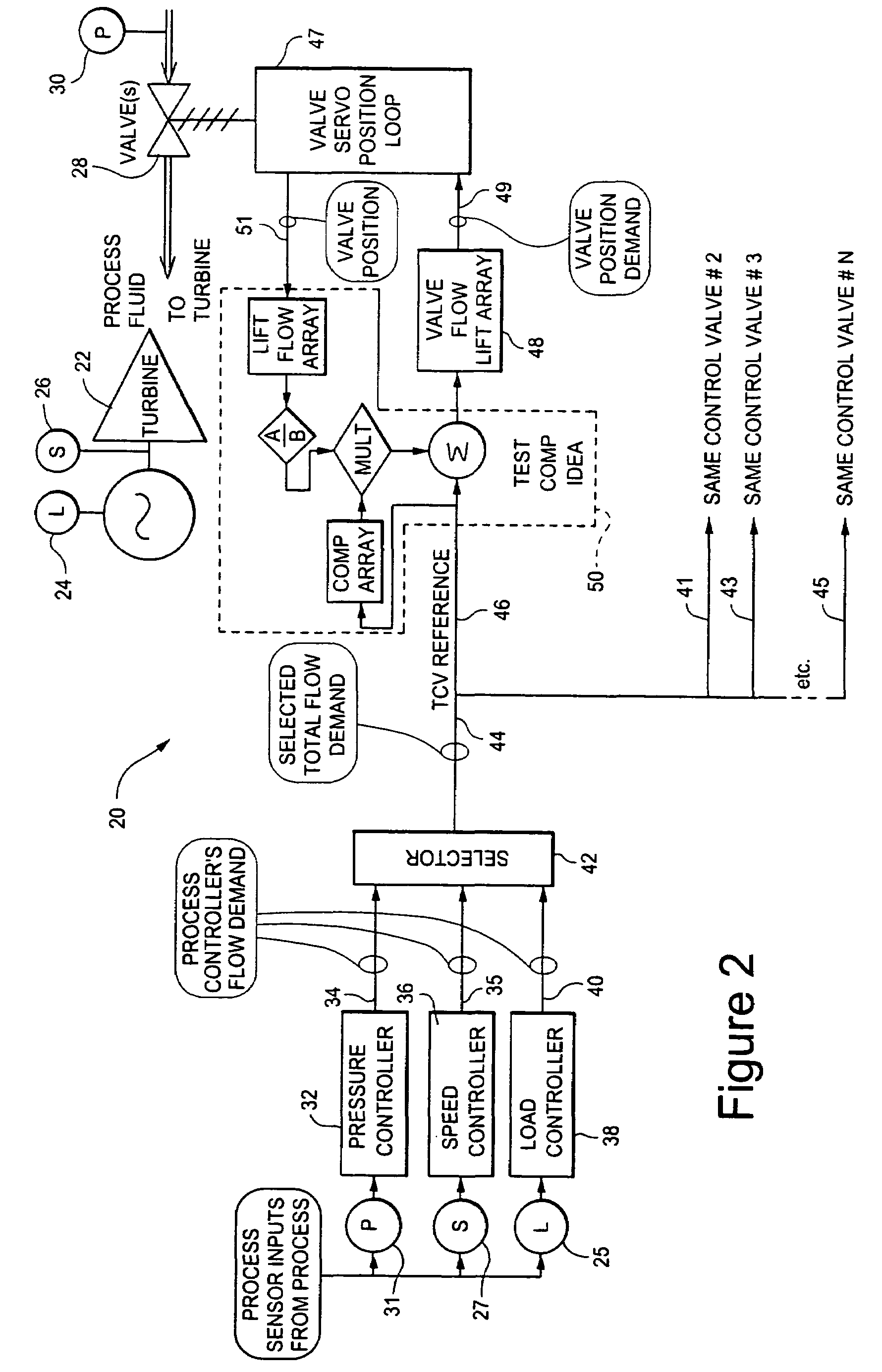
[0004]The present invention is a method of minimizing steam boiler pressure changes or turbine power changes during turbine control valve operational safety test stroking. The method of the present invention uses control valve positions as feedback to minimize flow disturbance caused by the closing and reopening of a turbine control valve during periodic operational testing. By maintaining the total mass flow through several parallel turbine inlet flow control valves constant, the steam generator pressure is maintained constant, and the inlet pressure regulator is unaffected during inlet control valve testing. Maintaining the total mass flow through several parallel turbine inlet control valves constant minimizes turbine power changes during inlet control valve testing. The position (valve stem lift or stroke) of the individual parallel valves is already present because it is used for closed-loop control of the inlet control valve positions. The valve position is sufficient, and results in improved performance, for the purpose of maintaining constant total flow when the method described herein is utilized. The monitoring of the available or additional process parameters for the purpose of reducing flow disturbance during inlet control valve testing, is not needed.

Problems solved by technology

One problem with such testing is changes in the turbine steam boiler pressure or changes in turbine power as a result of the closing and reopening of the turbine control valves during the periodic operational test.
The inlet pressure regulator design is defined and required by the steam boiler design and, thus, cannot be modified.
Neither of these methods may be applied to the inlet pressure problem because they both allow inlet pressure to change.

Method used


Image

  • Flow compensation for turbine control valve test
  • Flow compensation for turbine control valve test
  • Flow compensation for turbine control valve test

Examples


Embodiment Construction

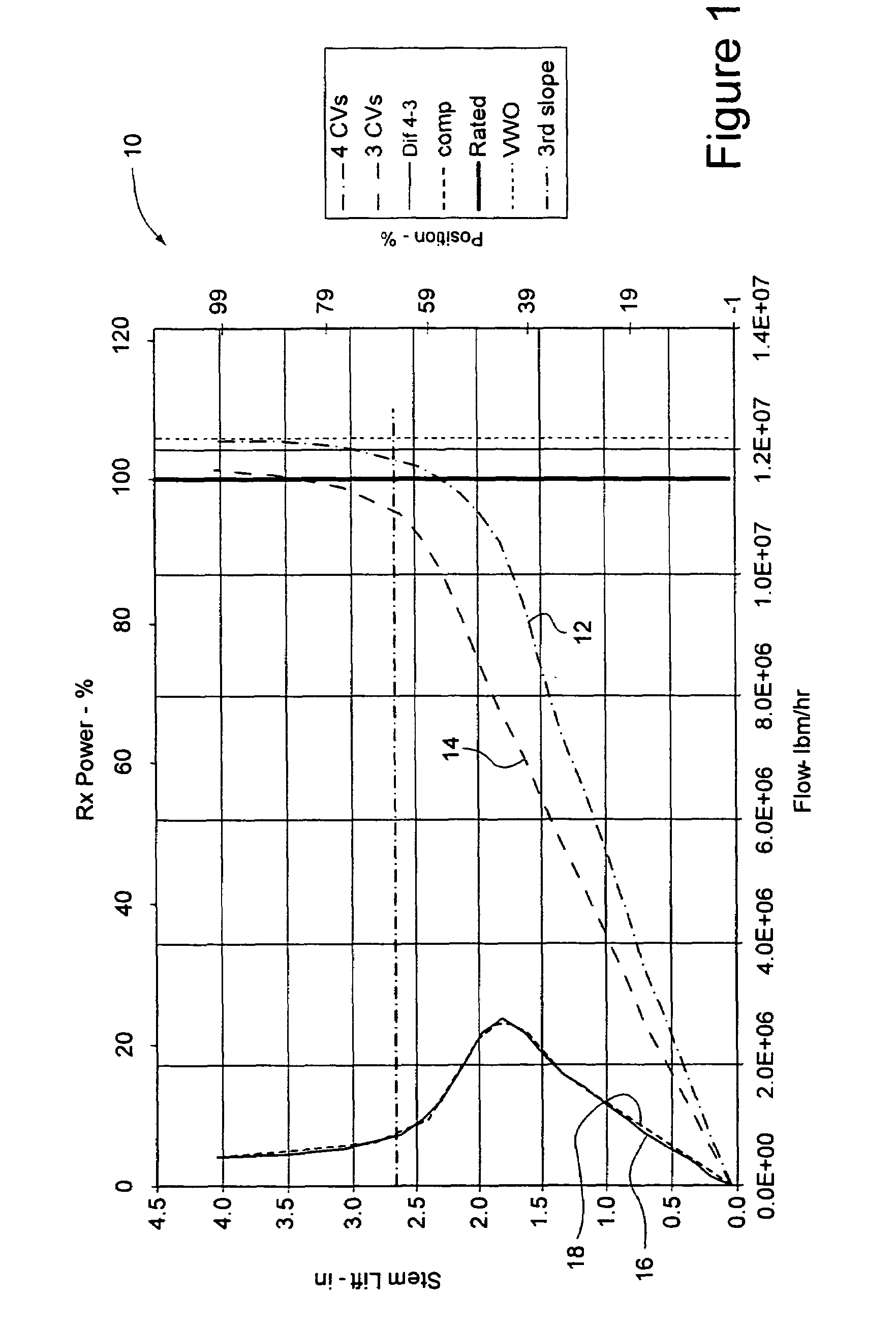
[0012]The present invention is a method of using control valve position as feedback into a compensation function to minimize flow disturbance caused by the closing and reopening of a turbine control valve during periodic operational testing. According to the method of the present invention, total mass flow for N parallel flow valves is calculated as a function of control valve position (valve stem lift). The flow change due to closure of one of the N parallel flow valves during valve tests, results in change of the system that is controlling pressure from N valves, to N-1 valves. The flow characteristic for each valve of the system with N valves, and for the system with N-1 valves, is determined during design. The flow characteristics are based on total flow (valve) demand. For any given valve not under test, the flow difference characteristic between the N and the N-1 condition is known.

[0013]FIG. 1 is a graph 10 showing the difference in flow characteristics between N and N-1 turb...


PUM


Abstract

The present invention is a method of minimizing steam boiler pressure changes or turbine power changes during turbine control valve operational safety test stroking. The method of the present invention uses control valve positions as feedback into a compensation algorithm to minimize flow disturbance caused by the closing and reopening of a turbine control valve during periodic operational testing. By maintaining the total mass flow through several parallel turbine inlet control valves constant, the steam generator pressure is maintained constant, and the inlet pressure regulator is unaffected during inlet control valve testing. Maintaining the total mass flow through several parallel turbine inlet control valves constant also minimizes turbine power changes during inlet control valve testing. In addition, the monitoring of additional process parameters is not needed. The position (valve stem lift) of the individual parallel valves is used for closed loop control of inlet valve position, and is sufficient for the purpose of maintaining constant flow.

Description

[0001]The present invention relates to turbines, and, in particular, to a method of minimizing flow disturbance caused by the closing and reopening of turbine control valves during periodic operational testing, and specifically, to using control valve positions as feedback to minimize such flow disturbance.BACKGROUND OF THE INVENTION[0002]Required operating procedure for turbines includes periodic operational testing (closing and reopening) of parallel inlet flow control valves used in turbines. The testing is done to confirm operability of turbine safety mechanisms. One problem with such testing is changes in the turbine steam boiler pressure or changes in turbine power as a result of the closing and reopening of the turbine control valves during the periodic operational test. Steam boiler pressure changes or turbine power changes must be minimized during turbine control valve operational safety test stroking. When present, the turbine inlet pressure regulation or turbine power fee...

Claims


Application Information

Patent Timeline
Patent Type & Authority Patents(United States)
IPC IPC(8): F04D27/02F04D27/00F01D17/18F01D21/00
CPCF01D17/18F01D21/003F05D2220/31F01D17/00F01D17/145G01M15/00
Inventor MOLITOR, MICHAEL JAMES
Owner GE INFRASTRUCTURE TECH INT LLC
Learn More